


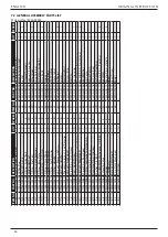


4.2 STANDARD NOSE ASSEMBLY SELECTION
The fasteners below can also be placed on the 73200 tool. It is essential that the correct nose assembly is fitted prior to
operating the tool.
STANDARD NOSE ASSEMBLY SELECTION
FASTENER
NOSE EQUIPMENT
NAME
Ø
DESCRIPTION
PART NO.
AVBOLT®
3/16" (4.8mm)
Refer to 07900-00905 datasheet
07220-08100
1/4" (6.4mm)
Refer to 07900-00905 datasheet
07220-07500
AVSEAL® II
11mm Standard
For Nose Tip selection refer to 07900-00840 datasheet
07220-06600
12mm Standard
For Nose Tip selection refer to 07900-00840 datasheet
07220-06700
13mm Low Pressure For Nose Tip selection refer to 07900-00840 datasheet
07220-06600
14mm Low Pressure For Nose Tip selection refer to 07900-00840 datasheet
07220-06700
16mm Low Pressure For Nose Tip selection refer to 07900-00840 datasheet
07220-06800 ∆
INTERLOK®
3/8” (10mm)
Standard straight equipment
73200-04500 †
MAXLOK®
1/4” (6.4mm)
Standard straight equipment
*07610-02100
3/16” (4.8mm)
Standard straight equipment
*07610-02000
MONOBOLT®
3/8" (10mm)
Standard Nose Tip
07220-07200 †
∆ Air inlet pressure of 7.0 bar required.
† Two tool actuations are needed to place these fasteners.
*
It is necessary to use adaptor kit (part number 73200-04300) to fit these nose assemblies to the tool.
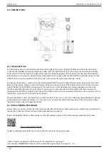
4.3 FITTING INSTRUCTIONS
CAUTION:
The air supply must be disconnected when fitting or removing nose assemblies unless specifically
instructed otherwise.
Nose assemblies must be pre-assembled before fitting.
STRAIGHT HORIZONTAL, VERTICAL OR ROUND NOSE ASSEMBLIES
•
Lightly coat the jaws with Moly Lithium grease.
•
Assemble Spring Guides
4
and Spring
5
•
Balance the three Chuck Jaws
3
on the upper Spring guide
4
(using a spent pintail to aid positioning if necessary)
•
Carefully lower Chuck Collect
2
over the assembled components
•
Insert Spacer
6
(if required) into Chuck Collet 2 (5/16” dia only)
•
Assembly can then be located in anvil
Item numbers in
bold
refer to the drawing opposite.
Fig. 4
12
ENGLISH
ORIGINAL INSTRUC TION
Содержание 73200
Страница 8: ...2 3 TOOL DIMENSIONS Fig 1 All dimensions are shown in millimetres 8 ENGLISH ORIGINAL INSTRUCTION ...
Страница 21: ...7 GENERAL ASSEMBLIES 7 1 GENERAL ASSEMBLY OF BASE TOOL 73200 02000 21 ORIGINAL INSTRUCTION ENGLISH ...
Страница 63: ...63 TRADUCTION DES INSTRUCTIONS ORIGINALES FRANÇAIS ...
Страница 95: ...95 TRADUCCIÓN A PARTIR DE INSTRUCCIONES ORIGINALES ESPAÑOL ...
Страница 116: ...7 CONJUNTO GERAL 7 1 CONJUNTO GERAL DA FERRAMENTA DE BASE 73200 02000 116 PORTUGUÊS TRADUÇÃO DAS INSTRUÇÕES ORIGINAIS ...
Страница 127: ...127 TRADUÇÃO DAS INSTRUÇÕES ORIGINAIS PORTUGUÊS ...