DEDEDEDEDEDEDEDEDEDEDEDEDEDEDEDEDEDEDEDEDEDEDEDEDE
Betriebsanleitung
Additional languages r-stahl.com
DE
Anschlussboard und Verbindungskabel
für Zone 2
Reihe 9491
– Für künftig
e Verwend
ung aufbew
ahren! –
Страница 1: ...E DE DE DE DE DE DE DE DE DE DE DE DE DE DE DE DE DE DE DE DE DE Betriebsanleitung Additional languages r stahl com DE Anschlussboard und Verbindungskabel für Zone 2 Reihe 9491 Für künftige Verwendung aufbewahren ...
Страница 2: ...cherheit 5 3 1 Bestimmungsgemäße Verwendung 5 3 2 Qualifikation des Personals 5 3 3 Restrisiken 6 4 Transport und Lagerung 8 5 Produktauswahl und Projektierung 8 5 1 Produktauswahl 8 6 Montage und Installation 9 6 1 Montage Demontage 9 6 2 Installation 10 7 Parametrierung und Inbetriebnahme 16 8 Betrieb 16 9 Instandhaltung Wartung Reparatur 16 9 1 Instandhaltung 16 9 2 Wartung 16 9 3 Reparatur 16 ...
Страница 3: ...gänglich machen Betriebsanleitung an jeden folgenden Besitzer oder Benutzer des Geräts weitergeben Betriebsanleitung bei jeder von R STAHL erhaltenen Ergänzung aktualisieren ID Nr 276285 949160310010 Publikationsnummer 2021 05 06 BA00 III de 00 Die Originalbetriebsanleitung ist die deutsche Ausgabe Diese ist rechtsverbindlich in allen juristischen Angelegenheiten 1 3 Weitere Dokumente Datenblatt B...
Страница 4: ...tbeachtung der Sicherheitsmaßnahmen zu schweren Verletzungen führen kann VORSICHT Gefahrensituation die bei Nichtbeachtung der Sicherheitsmaßnahmen zu leichten Verletzungen führen kann HINWEIS Gefahrensituation die bei Nichtbeachtung der Sicherheitsmaßnahmen zu Sachschäden führen kann Symbol Bedeutung 05594E00 CE Kennzeichnung gemäß aktuell gültiger Richtlinie 02198E00 Gerät gemäß Kennzeichnung fü...
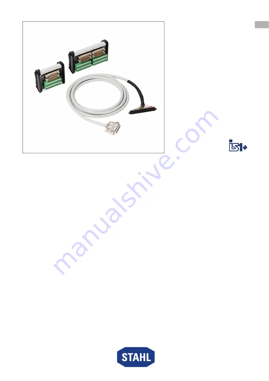
Страница 5: ...ung von nicht eigensicheren Feldstromkreisen zweier IS1 I O Module gleichen Typs Sie ermöglichen dadurch I O Module Redundanz Ebenso dürfen zur Verbindung von Anschlussboard und I O Modul nur Verbindungskabel Typ 9491 Z1 verwendet werden Zur bestimmungsgemäßen Verwendung gehören diese Betriebsanleitung und die mitgeltenden Dokumente z B das Datenblatt Alle anderen Anwendungen des Geräts sind nicht...
Страница 6: ...sein Gerät ausschließlich in besonderer Transportverpackung befördern die das Gerät vor äußeren Einflüssen sicher schützt Bei der Auswahl der Transportverpackung Umgebungsbedingungen siehe Kapitel Technische Daten berücksichtigen Verpackung und Gerät auf Beschädigung prüfen Beschädigungen umgehend an R STAHL melden Beschädigtes Gerät nicht in Betrieb nehmen Gerät in Originalverpackung trocken kein...
Страница 7: ...betriebnahme Instandhaltung oder Reinigung des Geräts dürfen nur nach gültigen nationalen Bestimmungen des Einsatzlandes und von qualifizierten Personen durchgeführt werden Ansonsten kann der Explosionsschutz aufgehoben werden Explosionen mit tödlichen oder schweren Verletzungen von Personen können die Folge sein Montage Installation Inbetriebnahme und Instandhaltung nur durch qualifizierte und au...
Страница 8: ...l 6 Keine separate Hilfsenergie erforderlich Die maximale Anzahl an I O Modulen auf der BusRail reduziert sich um die Zahl der redundanten I O Modul Paare Systemvoraussetzungen und Verhalten bei I O Modul Redundanz sind in der jeweiligen Kopplungsbeschreibung IS1 beschrieben 5 1 Produktauswahl Die Auswahl des passenden Anschlussboards und des Verbindungskabels ist von folgenden Bedingungen abhängi...
Страница 9: ...ger Gebrauchslage auf einer Hutschiene montiert werden 22370E00 Das Verbindungskabel Typ 9491 Z1 VB kann in beliebiger Gebrauchslage montiert werden 6 1 2 Montage Demontage von Gerät auf Hutschiene Montage 22371E00 Gerät mit beiden Aussparungen des Gehäuses oben auf die Außenkante der Hutschiene ansetzen 1 Gerät schwenken und mit etwas Druck auf die Hutschiene einrasten 1 2 Vergewissern dass das G...
Страница 10: ...esondere auf Schiffen sind zusätzliche Maßnahmen zur korrekten Installation je nach Einsatzort zu treffen Weitere Informationen und Anweisungen hierzu erhalten Sie gerne auf Anfrage von Ihrem zuständigen Vertriebskontakt GEFAHR Explosionsgefahr durch Zündfunken bei Arbeiten an einem nicht sicher befestigten Gerät Nichtbeachten führt zu tödlichen oder schweren Verletzungen Schrauben mit angegebenen...
Страница 11: ... Klemme am Kabelende auf die Klemme X1 des primären und redundanten I O Moduls aufstecken und mit den Sicherungsschrauben gegen Lockern sichern Anzugsdrehmoment 0 5 0 6 Nm Das Kabelende mit dem Sub D Stecker vom primären I O Modul Klemme X1 auf die Sub D Buchse X1P am Anschlussboard anschließen und mit den Sicherungsschrauben gegen Lockern sichern Anzugsdrehmoment 0 5 0 6 Nm Das Kabelende mit dem ...
Страница 12: ...und X1B des Anschlussboards weitergegeben 9469 35 08 11 9491 T1 08 0 Kanal Klemme Klem men Nr Funktion Klemme Klem men Nr 2 Leiter MU AI AO 3 4 Leiter MU AI ext Versorgung 0 X1 1 NC X1A 1 2 Masse GND NC 2 1 3 NC 3 4 Masse GND NC 4 2 5 NC 5 6 Masse GND NC 6 3 7 NC 7 8 Masse GND NC 8 4 9 NC Ausgang 24 V 9 10 10 11 NC 11 12 Masse GND Masse GND 12 5 13 NC Ausgang 24 V X1B 1 14 2 15 NC 3 16 Masse GND M...
Страница 13: ...2 auf die Sub D Buchse X2P am Anschlussboard anschließen und mit den Sicherungsschrauben gegen Lockern sichern Anzugsdrehmoment 0 5 0 6 Nm Die Kabelenden mit dem Sub D Stecker vom redundanten I O Modul Klemme X1 auf die Sub D Buchse X1R und Klemme X2 auf die Sub D Buchse X2R am Anschlussboard anschließen und mit den Sicherungsschrauben gegen Lockern sichern Anzugsdrehmoment 0 5 0 6 Nm GEFAHR Explo...
Страница 14: ... Klemme Klem men Nr Funktion DO Klemme Klem men Nr 9472 35 16 11 9471 35 16 11 0 X1 1 Ausgang 24 V NC X1A 1 2 Signal Signal 2 3 Masse GND Masse GND 3 1 4 Ausgang 24 V NC 4 5 Signal Signal 5 6 Masse GND Masse GND 6 2 7 Ausgang 24 V NC 7 8 Signal Signal 8 9 Masse GND Masse GND 9 3 10 Ausgang 24 V NC 10 11 Signal Signal 11 12 Masse GND Masse GND 12 4 13 Ausgang 24 V NC X1B 1 14 Signal Signal 2 15 Mas...
Страница 15: ...e Klem men Nr 9472 35 16 11 9471 35 16 11 8 X2 25 Ausgang 24 V NC X2A 1 26 Signal Signal 2 27 Masse GND Masse GND 3 9 28 Ausgang 24 V NC 4 29 Signal Signal 5 30 Masse GND Masse GND 6 10 31 Ausgang 24 V NC 7 32 Signal Signal 8 33 Masse GND Masse GND 9 11 34 Ausgang 24 V NC 10 35 Signal Signal 11 36 Masse GND Masse GND 12 12 37 Ausgang 24 V NC X2B 1 38 Signal Signal 2 39 Masse GND Masse GND 3 13 40 ...
Страница 16: ...er Prüfung Gerät in Betrieb nehmen 8 Betrieb 9 Instandhaltung Wartung Reparatur Geltende nationale Normen und Bestimmungen im Einsatzland beachten z B IEC EN 60079 14 IEC EN 60079 17 IEC EN 60079 19 9 1 Instandhaltung Ergänzend zu den nationalen Regeln folgende Punkte prüfen Rissbildung und andere sichtbare Schäden am Gerätegehäuse und oder Schutzgehäuse Einhaltung der zulässigen Temperaturen fest...
Страница 17: ...HL Schaltgeräte GmbH senden Adresse siehe Kapitel 1 1 11 Reinigung Die Platine mit den Steckverbindern nicht reinigen Gerät vor und nach der Reinigung auf Beschädigung prüfen Beschädigte Geräte sofort außer Betrieb nehmen Zur Vermeidung elektrostatischer Aufladung dürfen die Geräte in explosionsgefährdeten Bereichen nur mit einem feuchten Tuch gereinigt werden Gerät nur mit feuchtem Tuch und ohne ...
Страница 18: ...nd im sicheren Bereich Weitere Angaben siehe jeweilige Bescheinigung und Betriebsanleitung Technische Daten Ausführung Typ 9491 T1 08 0 Typ 9491 T1 16 0 Elektrische Daten Signaltyp Analog Eingang Ausgang Digital Ausgang Signalart 2 Leiter AI AO 3 4 Leiter AI 24 V 0 5 A DO Low power 6 V 2 mA DO Kanäle 8 16 Nennspannung UN analog 21 V DC Nenntrom analog In Out 0 24 mA Nennspannung UN digital 24 V DC...
Страница 19: ...h folgenden Normen und Vorschriften EN 61326 1 Einsatz im industriellen Bereich NAMUR NE 21 Umgebungsbedingungen Umgebungs temperatur 40 75 C Lagertemperatur 40 80 C Maximale relative Luftfeuchte 95 ohne Betauung Maximale Betriebshöhe 2000 m Mechanische Daten Schutzart IEC 60529 IP20 Modulgehäuse Polyamid 6GF Brandfestigkeit UL 94 V2 Schadstoffklasse entspricht G3 Abisolierlänge min 9 mm Gewicht 0...
Страница 20: ...gskontakt Elektrische Verbindung Kabelschirm mit Hutschiene 2 Schnappriegel Zur Befestigung des Geräts auf die Hutschiene 3 Sub D Buchse X1P Zum Anschluss an I O Modul 4 Sub D Buchse X1R Zum Anschluss an I O Modul 5 Klemme X1B Zur feldseitigen Verdrahtung 6 Klemme X1A Zur feldseitigen Verdrahtung 7 Sub D Buchse X2P Zum Anschluss an I O Modul 8 Sub D Buchse X2R Zum Anschluss an I O Modul 9 Klemme X...
Страница 21: ...Reihe 9491 15 2 Maßangaben Befestigungsmaße Maßzeichnungen alle Maße in mm Zoll Änderungen vorbehalten 22230E00 22231E00 Typ 9491 T1 08 0 Typ 9491 T1 16 0 48 50 1 91 101 40 3 99 92 30 3 63 1 2 3 4 5 6 7 8 9 10 11 12 1 2 3 4 5 6 7 8 9 10 11 12 153 6 02 1 2 3 4 5 6 7 8 9 10 11 12 1 2 3 4 5 6 7 8 9 10 11 12 1 2 3 4 5 6 7 8 9 10 11 12 1 2 3 4 5 6 7 8 9 10 11 12 92 30 3 63 48 50 1 91 ...
Страница 22: ......
Страница 23: ...N EN EN EN EN EN EN EN EN EN EN EN EN EN EN EN EN EN EN EN EN EN EN Operating instructions Additional languages r stahl com EN Termination board and connecting cable for Zone 2 Series 9491 Save for future use ...
Страница 24: ...evice 4 3 Safety 5 3 1 Intended Use 5 3 2 Personnel Qualification 5 3 3 Residual Risks 6 4 Transport and Storage 8 5 Product Selection and Project Engineering 8 5 1 Product Selection 8 6 Mounting and Installation 9 6 1 Mounting Dismounting 9 6 2 Installation 10 7 Parameterization and Commissioning 16 8 Operation 16 9 Maintenance Overhaul Repair 16 9 1 Maintenance 16 9 2 Overhaul 16 9 3 Repair 16 1...
Страница 25: ...d maintenance personnel at all times Pass the operating instructions on to each subsequent owner or user of the device Update the operating instructions every time you receive an amendment to them from R STAHL ID No 276285 949160310010 Publication Code 2021 05 06 BA00 III en 00 The original instructions are the German edition They are legally binding in all legal affairs 1 3 Further Documents Data...
Страница 26: ...tion which can result in severe injuries if the safety measures are not complied with CAUTION Dangerous situation which can result in minor injuries if the safety measures are not complied with NOTICE Dangerous situation which can result in material damage if the safety measures are not complied with Symbol Meaning 05594E00 CE marking in accordance with the current applicable directive 02198E00 De...
Страница 27: ...ching of non intrinsically safe field circuits for two IS1 I O modules of the same type They thereby enable I O module redundancy Likewise only type 9491 Z1 connecting cables can be used to connect the termination board and I O module Intended use includes complying with these operating instructions and the other applicable documents e g the data sheet Any other use of the device is not intended 3...
Страница 28: ... packaging that reliably protects the device from external influences Observe the ambient conditions when selecting the transport packaging see the Technical data chapter Check the packaging and the device for damage Report any damage to R STAHL immediately Do not commission a damaged device Store the device in its original packaging in a dry place with no condensation and make sure that it is sta...
Страница 29: ...pplicable national regulations of the country of use and only by qualified persons Otherwise the explosion protection may be rendered ineffective This may result in explosions causing serious or even fatal injury Have the assembly installation commissioning and maintenance work performed by qualified and authorised persons only see chapter 3 2 Observe the correct mounting position see the Mounting...
Страница 30: ...parate auxiliary power is required The maximum number of I O modules on the BusRail is reduced by the number of redundant I O module pairs The system requirements and behaviour with I O module redundancy are described in the corresponding IS1 coupling description 5 1 Product Selection The selection of the suitable termination board and connecting cable depends on the following conditions Type and ...
Страница 31: ...lled in any operating position on a DIN rail 22370E00 The type 9491 Z1 VB connecting cable can be installed in any operating position 6 1 2 Mounting Dismounting of the Device on DIN Rail Mounting 22371E00 Position the device with both cut outs in the enclosure at the top on the outer edge of the DIN rail 1 Swing the device towards the DIN rail and then use a small amount of force to snap it into p...
Страница 32: ...ar on ships requires additional measures to be taken for correct installation depending on the operating location Further information and instructions on this can be obtained from your regional sales contact upon request DANGER Explosion hazard due to ignition sparks during work on a device that has not been fitted securely Non compliance may result in fatal or serious injuries Tighten the screws ...
Страница 33: ... the cable end on the X1 terminals of the primary and redundant I O modules and use the safety screws to secure it from loosening tightening torque 0 5 to 0 6 Nm Connect the cable end with the Sub D plug from the primary I O module terminal X1 to the Sub D socket X1P on the termination board and use the safety screws to secure it against loosening tightening torque 0 5 to 0 6 Nm Connect the cable ...
Страница 34: ...ules are passed on to the X1A and X1B terminals of the termination board 9469 35 08 11 9491 T1 08 0 Channel Terminal Terminal no Function Terminal Terminal no 2 wire AI AO transmitter 3 4 wire AI transmitter ext supply 0 X1 1 NC X1A 1 2 Earth NC 2 1 3 NC 3 4 Earth NC 4 2 5 NC 5 6 Earth NC 6 3 7 NC 7 8 Earth NC 8 4 9 NC Output 24 V 9 10 10 11 NC 11 12 Earth Earth 12 5 13 NC Output 24 V X1B 1 14 2 1...
Страница 35: ... X2 to Sub D socket X2P on the termination board and use the safety screws to secure it against loosening tightening torque 0 5 to 0 6 Nm Connect the cable ends with the Sub D plug from the redundant I O module terminal X1 to the Sub D socket X1R and from terminal X2 to Sub D socket X2R on the termination board and use the safety screws to secure it against loosening tightening torque 0 5 to 0 6 N...
Страница 36: ... board 9471 35 and 9472 35 9491 T1 16 0 Channel Terminal Terminal no Function DO Terminal Terminal no 9472 35 16 11 9471 35 16 11 0 X1 1 Output 24 V NC X1A 1 2 Signal Signal 2 3 Earth Earth 3 1 4 Output 24 V NC 4 5 Signal Signal 5 6 Earth Earth 6 2 7 Output 24 V NC 7 8 Signal Signal 8 9 Earth Earth 9 3 10 Output 24 V NC 10 11 Signal Signal 11 12 Earth Earth 12 4 13 Output 24 V NC X1B 1 14 Signal S...
Страница 37: ...el Terminal Terminal no Function DO Terminal Terminal no 9472 35 16 11 9471 35 16 11 8 X2 25 Output 24 V NC X2A 1 26 Signal Signal 2 27 Earth Earth 3 9 28 Output 24 V NC 4 29 Signal Signal 5 30 Earth Earth 6 10 31 Output 24 V NC 7 32 Signal Signal 8 33 Earth Earth 9 11 34 Output 24 V NC 10 35 Signal Signal 11 36 Earth Earth 12 12 37 Output 24 V NC X2B 1 38 Signal Signal 2 39 Earth Earth 3 13 40 Ou...
Страница 38: ...ully tested 8 Operation 9 Maintenance Overhaul Repair Comply with the applicable national standards and regulations in the country of use e g IEC EN 60079 14 IEC EN 60079 17 IEC EN 60079 19 9 1 Maintenance Check the following points in addition to the national regulations Whether the device enclosure and or protective enclosure has have cracks or other visible signs of damage Whether the permissib...
Страница 39: ...bH refer to chapter 1 1 for the address 11 Cleaning Do not clean the PCB with the plug connectors Check the device for damage before and after cleaning it Take damaged devices out of operation immediately To avoid electrostatic charging the devices located in hazardous areas may only be cleaned using a damp cloth Gently clean the device only with a damp cloth and without scratching abrasive or agg...
Страница 40: ...nformation see respective certificate and operating instructions Technical Data Version Type 9491 T1 08 0 Type 9491 T1 16 0 Electrical data Signal type Analogue input output Digital output Signal type 2 wire AI AO 3 4 wire AI 24 V 0 5 A DO Low power 6 V 2 mA DO Channels 8 16 Nominal voltage UN analogue 21 V DC Nominal current analogue In Out 0 to 24 mA Nominal voltage UN digital 24 V DC 18 to 32 V...
Страница 41: ...tandards and regulations EN 61326 1 For use in industrial areas NAMUR NE 21 Ambient conditions Ambient temperature 40 to 75 C Storage temperature 40 to 80 C Maximum relative humidity 95 without condensation Maximum operating height 2000 m Mechanical data Degree of protection IEC 60529 IP20 Module enclosure Polyamide 6GF Fire resistance UL 94 V2 Pollutant class corresponds to G3 Stripping length mi...
Страница 42: ...rthing contact Electrical connection between cable shield and DIN rail 2 Snap catch For mounting the device on the DIN rail 3 Sub D socket X1P For connection to the I O module 4 Sub D socket X1R For connection to the I O module 5 Terminal X1B For field side wiring 6 Terminal X1A For field side wiring 7 Sub D socket X2P For connection to the I O module 8 Sub D socket X2R For connection to the I O m...
Страница 43: ...491 15 2 Dimensions Fastening Dimensions Dimensional drawings all dimensions in mm inches Subject to alteration 22230E00 22231E00 Type 9491 T1 08 0 Type 9491 T1 16 0 48 50 1 91 101 40 3 99 92 30 3 63 1 2 3 4 5 6 7 8 9 10 11 12 1 2 3 4 5 6 7 8 9 10 11 12 153 6 02 1 2 3 4 5 6 7 8 9 10 11 12 1 2 3 4 5 6 7 8 9 10 11 12 1 2 3 4 5 6 7 8 9 10 11 12 1 2 3 4 5 6 7 8 9 10 11 12 92 30 3 63 48 50 1 91 ...
Страница 44: ......