DEDEDEDEDEDEDEDEDEDEDEDEDEDEDEDEDEDEDEDEDEDEDEDEDE
Betriebsanleitung
Additional languages r-stahl.com
DE
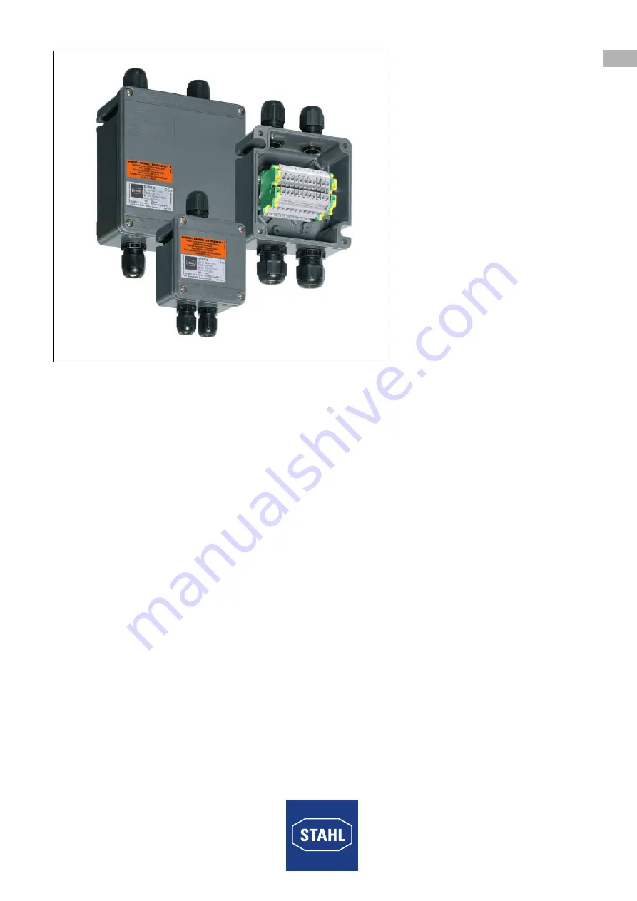
Klemmenkästen
Reihe 8118/1, Reihe 8118/2
– Für kü
nftige Ve
rwendun
g aufbew
ahren! –
Страница 1: ...DE DE DE DE DE DE DE DE DE DE DE DE DE DE DE DE DE DE DE DE DE DE DE DE Betriebsanleitung Additional languages r stahl com DE Klemmenk sten Reihe 8118 1 Reihe 8118 2 F r k nftige Verwendung aufbewahr...
Страница 2: ...ualifikation des Personals 5 3 3 Restrisiken 6 4 Transport und Lagerung 8 5 Produktauswahl Projektierung und Modifikation 8 5 1 Zus tzliche Bohrungen 9 5 2 u ere Anbaukomponenten Leitungseinf hrungen...
Страница 3: ...nd der Lebensdauer des Ger ts aufbewahren Betriebsanleitung dem Bedien und Wartungspersonal jederzeit zug nglich machen Betriebsanleitung an jeden folgenden Besitzer oder Benutzer des Ger ts weitergeb...
Страница 4: ...icherheitsma nahmen zum Tod oder zu schweren Verletzungen mit bleibenden Sch den f hren kann WARNUNG Gefahrensituation die bei Nichtbeachtung der Sicherheitsma nahmen zu schweren Verletzungen f hren k...
Страница 5: ...denen Gr en hergestellt Sie m ssen ortsfest montiert werden Die eingebauten Komponenten sind separat zertifiziert Zur bestimmungsgem en Verwendung geh rt die Beachtung dieser Betriebsanleitung und der...
Страница 6: ...ssig tragen k nnen Ger t nicht belasten Verpackung und Ger t auf Besch digung pr fen Besch digungen umgehend an R STAHL melden Ger t in Originalverpackung trocken keine Betauung in stabiler Lage und...
Страница 7: ...nen k nnen die Folge sein Montage Installation Inbetriebnahme und Instandhaltung nur durch qualifizierte und autorisierte Personen siehe Kapitel 3 2 durchf hren lassen nderungen am Ger t nur entsprech...
Страница 8: ...g des Ger ts Nichtbeachten f hrt zu t dlichen oder schweren Verletzungen Ger t nicht lackieren Ausbesserungen nur durch den Hersteller vornehmen lassen GEFAHR Explosion durch fehlerhafte Abdichtung de...
Страница 9: ...ten wie z B durch die zus tzlich einzubauenden Komponenten ge ndert haben 5 1 2 Zus tzliche Bohrungen durch den Kunden anbringen 5 1 2 1 Geh use Nutzbare Fl che f r Leitungseinf hrungen im Geh use ber...
Страница 10: ...siehe Kapitel Sicherheit ver ndern Nutzbare Fl che f r Einbaukomponenten berechnen Zus tzliche Bohrungen durch Lasern oder Stanzen Bohren Lochschneiden einbringen Dabei Abstand von mind 10 mm zum Rand...
Страница 11: ...ellen Werten anbringen 5 2 u ere Anbaukomponenten Leitungseinf hrungen Verschlussstopfen Klimastutzen 5 2 1 Anbaukomponenten durch R STAHL anbringen An R STAHL folgende Informationen bermitteln Typ Da...
Страница 12: ...cht fest verlegten Leitungen Leitungseinf hrungen mit Zugentlastung Verschluss unbenutzter Einf hrungs ffnungen Verschlussstopfen entsprechend der Z ndschutzart verwenden Entw sserung und Druckausglei...
Страница 13: ...8 112 8118 114 8118 122 8118 124 Durch die bergangswiderst nde an Klemmstellen und durch die im Geh use verlegten Leitungen entsteht W rme Damit die maximal zul ssige Temperatur des Geh uses nicht ber...
Страница 14: ...R STAHL anbringen An R STAHL folgende Informationen weitergeben Typ Hersteller Datenblatt Anzahl Geh usegr e R STAHL pr ft ob Klemmentyp Anzahl Querschnitt und Strombelastung der Zulassung entsprechen...
Страница 15: ...itel Sicherheit ver ndern Zus tzliche Klemmstellen Klemmentyp Anzahl Querschnitt und Strombelastung ermitteln siehe Kapitel Technische Daten Pr fen ob sich durch die Nachbest ckung die Typschilddaten...
Страница 16: ...en f r folgende max zul ssige Oberfl chentemperaturen die Temperaturklassen der zugeh rigen Umgebungstemperaturwerte f r staubexplosionsgef hrdete Bereiche Betriebsspannung 275 V 20702E00 Betriebsspan...
Страница 17: ...trahlung sind zus tzliche Ma nahmen zur korrekten Installation je nach Einsatzort zu treffen Weitere Informationen und Anweisungen hierzu erhalten Sie gerne auf Anfrage von Ihrem zust ndigen Vertriebs...
Страница 18: ...ung Aderendh lsen fachgerecht und mit geeignetem Werkzeug anbringen Im Falle einer maximalen Best ckung mit Klemmen und stromf hrenden Leitern sowie maximalen Strombelastung Sicherstellen dass die L n...
Страница 19: ...sind ausreichend strombelastbar sind Sicherstellen dass nichtmetallische isolierende Trennw nde mindestens 0 9 mm dick sind die erforderliche Kriechstromzahl CTI aufweisen Dazu Norm IEC EN 60079 7 so...
Страница 20: ...r fen ob alle Abdeckungen und Trennw nde an spannungsf hrenden Teilen vorhanden und befestigt sind Sicherstellen dass alle ffnungen Bohrungen im Geh use mit daf r zul ssigen Komponenten verschlossen s...
Страница 21: ...pitel 1 1 10 Reinigung Ger t vor und nach der Reinigung auf Besch digung pr fen Besch digte Ger te sofort au er Betrieb nehmen Zur Vermeidung elektrostatischer Aufladung d rfen die Ger te in explosion...
Страница 22: ...D Ex tb IIIC T80 C T130 C Db Bescheinigungen und Zertifikate Bescheinigungen IECEx ATEX Technische Daten Ausf hrungen 8118 1 2 Ex e 8118 2 2 Ex i ohne Ger teschutzsicherung 8118 1 4 Ex e mit Ger tesch...
Страница 23: ...ndungsklemmen WAGO 221 20704E00 20705E00 20706E00 Art Nr 272622 Art Nr 272623 Art Nr 272624 Anzahl der Klemmstellen 2 3 5 Elektrische Daten Bemessungs betriebsspannung max 440 V Bemessungs betriebsstr...
Страница 24: ...zeichnungen alle Ma e in mm Zoll nderungen vorbehalten 04466E00 04467E00 04468E00 04469E00 8118 1 Baugr e 1 8118 2 Baugr e 2 8118 3 Baugr e 3 Zusatzma f r Kabelver schraubungen Reihe 8161 8 55 2 17 6...
Страница 25: ...EN EN EN EN EN EN EN EN EN EN EN EN EN EN EN EN EN EN EN EN EN EN EN EN EN Operating instructions Additional languages r stahl com EN Terminal Boxes Series 8118 1 Series 8118 2 Save for future use...
Страница 26: ...nnel Qualification 5 3 3 Residual Risks 6 4 Transport and Storage 8 5 Product Selection Project Engineering and Modification 8 5 1 Additional Drilled Holes 9 5 2 External Attached Components Cable Ent...
Страница 27: ...throughout the service life of the device Make the operating instructions accessible to operating and maintenance personnel at all times Pass the operating instructions on to each subsequent owner or...
Страница 28: ...fatal or severe injuries causing permanent damage if the safety measures are not complied with WARNING Dangerous situation which can result in severe injuries if the safety measures are not complied w...
Страница 29: ...ferent sizes They must be installed so they are stationary The installed components must be certified separately Intended use includes complying with these operating instructions and the other applica...
Страница 30: ...ce Check the packaging and the device for damage Report any damage to R STAHL immediately Store the device in its original packaging in a dry place with no condensation and make sure that it is stable...
Страница 31: ...Have the mounting installation commissioning and maintenance work performed by qualified and authorised persons only see chapter 3 2 Only make modifications to the device according to the instruction...
Страница 32: ...ce is completely painted after manufacture Non compliance may result in serious or even fatal injuries Do not paint the device Have all repairs performed by the manufacturer DANGER Explosion due to de...
Страница 33: ...due to the components that are to be additionally installed 5 1 2 Have the Customer create additional Drilled Holes 5 1 2 1 Enclosure Calculate the usable area for cable entries in the enclosure The...
Страница 34: ...information see Safety chapter Calculate the usable area for built in components Create additional drilled holes through lasing or punching drilling hole cutting When doing so maintain a distance of m...
Страница 35: ...ting plate with the current values 5 2 External Attached Components Cable Entries Stopping Plugs Breathers 5 2 1 Fitting of Attached Components by R STAHL Give the following information to R STAHL Typ...
Страница 36: ...at are not permanently installed Cable entries with strain relief Sealing unused entries Use stopping plugs that comply with the type of protection required Draining and equalising pressure Breather E...
Страница 37: ...55 C 8118 112 8118 114 8118 122 8118 124 Heat develops due to contact resistance at the clamping units and due to the electrical lines installed in the enclosure In order to ensure that the maximum pe...
Страница 38: ...erminals by R STAHL Forward the following information to R STAHL Type Manufacturer Data sheet Number Enclosure size R STAHL will check whether the terminal type number cross section and current load c...
Страница 39: ...apter Safety Ascertain additional terminal points terminal type quantity cross section and current load see Chapter Technical data Check whether the rating plate data is changed as a result of retrofi...
Страница 40: ...e ambient temperature values for areas with dust explosion hazard for the following max permissible surface temperatures apply Operating voltage 275 V 20702E00 Operating voltage 275 to 440 V 20700E00...
Страница 41: ...ensure that the device is installed correctly depending on the operating location Further information and instructions on this can be obtained from your regional sales contact upon request DANGER Exp...
Страница 42: ...end sleeves properly using a suitable tool If the system is equipped with all possible terminals and live conductors and the maximum current load has been reached ensure that the length of a conducto...
Страница 43: ...at least 0 45 mm thick are earthed are sufficiently strong and rigid have sufficient current carrying capacity Make sure that non metallic insulating partitions are at least 0 9 mm thick have the requ...
Страница 44: ...for live parts have been installed and fastened Make sure that all openings drilled holes in the enclosure are sealed with permissible components Dust and transport protection adhesive tape or plastic...
Страница 45: ...ss 10 Cleaning Check the device for damage before and after cleaning it Take damaged devices out of operation immediately To avoid electrostatic charging the devices located in hazardous areas may onl...
Страница 46: ...Ex tb IIIC T80 C T130 C Db Certifications and certificates Certificates IECEx ATEX Technical Data Versions 8118 1 2 Ex e 8118 2 2 Ex i without miniature fuse 8118 1 4 Ex e with miniature fuse Electri...
Страница 47: ...ype of terminals WAGO 221 connection terminals 20704E00 20705E00 20706E00 Art no 272622 Art no 272623 Art no 272624 Number of clamping points 2 3 5 Electrical data Rated operational voltage max 440 V...
Страница 48: ...wings all dimensions in mm inches Subject to modification 04466E00 04467E00 04468E00 04469E00 8118 1 Design size 1 8118 2 Design size 2 8118 3 Design size 3 Additional dimension for cable glands Serie...
Страница 49: ......