background image

Istruzioni, instructions 


19


Attention!


• 

This manual is for qualified technical personnel only for installation purposes and not 

intended for the end user; it’s the installer’s job to explain to the user how the automatism 

works, about possible hazards related to it and about the need for periodical 

maintenance.


• 

The automatism must be installed by qualified personnel only, observing current standards 

concerning automatic closing systems. More specifically, installation conformity calls for 

observance of directive 89/392 and standards EN 12453 and EN 12445. 


• 

As ALPHEO is made specifically to control swing gates it is forbidden to use the product for 

different purposes or improperly. 

• 

Use original components only. Stagnoli is not liable for damages if other components are 

used. 

• 

Make certain that the gate structure is solid and suitable for being motor-driven. 

• 

When the gate is moving make sure there are no points of friction and there is no chance 

of it derailing. 

• 

Make absolutely certain the power is disconnected before carrying out any work on the 

device. 

• 

Connect the power lead to supply lines with adequate electrical protection only; install a 

device to guarantee disconnection of all the phases from the mains that has a distance of 

at least 3.5 mm between the contacts. 

• 

Pay particular attention when deciding which safety devices to install and their location. 

Always install an emergency stop device that will cut power off in the case of necessity.  

• 

Only qualified personnel must be allowed to service the unit and access the internal parts 

of the geared motor. 


• 

Irreversibility of the geared motors means an electric lock does not have to be installed 

and, in the case of black-out the release device (protected by a personalised key) lets 

you open the gate by hand. We do however recommend using an electric lock to ensure 

correct closing especially if the swing gates are longer than 2.5 metres. 


Содержание ALPEHO 230

Страница 1: ...Istruzioni instructions 1 Motoriduttore a braccio snodato per cancelli battenti Gear motor with articulated arm for swing gates ALPHEO ...

Страница 2: ...or driven When the gate is moving make sure there are no points of friction and there is no chance of it derailing Make absolutely certain the power is disconnected before carrying out any work on the device Connect the power lead to supply lines with adequate electrical protection only install a device to guarantee disconnection of all the phases from the mains that has a distance of at least 3 5...

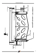
Страница 3: ...ctions 20 4x1 RX 2x1 2x1 TX 3x1 5 4x1 RX RG 58 2x1 5 2x1 TX 3x1 5 230 V ZEUS Transmitter POLIFEMO photocell PEGASUS Blinker ASM1 key select or ARGO Photocell ALPHEO 230 M ALPHEO 230V residential application ALPHEO 230 S ...

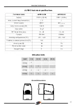
Страница 4: ... 3 1 Motor supply 230V 24V Max motor power W 160 W 120 W Capacitor 10 µF 90 Travel time sec 15 20 15 20 Torque 180 Nm 180 Nm Working temperature C 20 60 20 60 Thermal overload protection C 150 Work cycle 30 70 IP protection level 44 44 Weight Kg 9 10 Utilisation limits Overall dimensions 209 256 263 Leaf 1 m 1 5 m 2 m 2 3 m 300 kg 250 kg 225 kg 200 kg ...

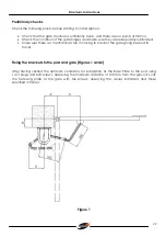
Страница 5: ...tely lubricated Make sure there is a mechanical stop in closing to prevent the gate going beyond its travel Fixing the brackets to the post and gate Figures 1 and 2 After having verified the optimum conditions for installation fix the Base Plate to the post using 14 plugs and M8 screws observing the minimum distance of 100 mm from the ground Lock the fastening plate to the gate with M6 screws obse...

Страница 6: ...ll anta Figure 2 OPENING A B C D 90 155 210 0 430 230 max 90 155 210 50 430 230 max 90 155 210 75 430 230 max 90 155 210 100 430 230 max 90 155 210 125 430 230 max 90 155 210 150 400 230 max 90 155 210 175 400 230 max 90 155 210 200 400 230 max 105 190 210 0 430 230 max 105 200 30 430 230 max ...

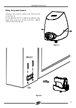
Страница 7: ...ons 24 Fixing the geared motor Unscrew the 4 2x9 5 screws and remove the cover Fig 3 Fit the geared motor on the base plate by the holes and lock it in place with the M8x90 screws and nuts Fig 4 Figure 3 M8x80 M8 Figure 4 ...

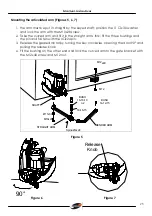
Страница 8: ...m s fork fit the three bushings and the pin and fasten with the 4 x24 pin 3 Release the geared motor by turning the key clockwise opening the door 90 and pulling the release knob 4 Fit the bushing on the other end and lock the curved arm to the gate bracket with the M12x40 screw and M12 nut Ø11x30 M10x28 Spina Ø4x24 M12x40 M12 BUSH 14 12 15 BUSH 18 16 10 n 2 18 16 15 SHAFT STRAIGHT ARM BENDED ARM ...

Страница 9: ...elettronica per motoriduttori elettromeccanici Control board for electromechanical gearmotors Centrale électronique pour motoréducteur électromécanique Elektronische Steuerung für elektromechanische Getriebemotor ULIXES 24V ALPHEO 24V ZEFIRO 24V Rev 0 11 05 ...

Страница 10: ... sure that the power supply has been cut off The feeding cable can be connected only with feeders supplied with proper electric protection In particular make sure that the distance between the contacts is of at least 3 5 mm in order to avoid omnipolar disconnection from the grid Take into consideration the safety devices to be installed and the place where they should be positioned Always have an ...

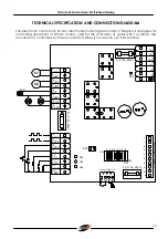
Страница 11: ...tivation of gates with 1 or 2 leafs the movement is controlled by the encoder and there is no need to use limit switches 1 VAC 2 VAC 3 BAT 5 24 6 24 7 4 BAT CONNETTORE MOLEX 8 APM1 12 ELS 13 COM1 14 LAMP 15 SP AP 9 CHM1 10 APM2 11 CHM2 16 ENC1 20 F CL 21 F OP 22 STOP 23 COM 17 ENC2 18 APED 19 APCH F1 F10A 250V F3 T1 6A 250V F2 T1 6A 250V DL4 DL3 DL2 DL5 SW OFF 1 2 3 4 5 6 7 8 24 25 26 27 CH2 GND S...

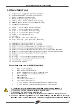
Страница 12: ...peration 21 Electric contact normally closed by the photocell for the opening operation 22 Electric contact normally closed by the Stop button 23 Common 24 2nd output radio channel unpolarized contact 25 2nd output radio channel unpolarized contact 26 Input antenna braided wire 27 Input antenna signal Connections radio card CONNECTOR MOLEX A Input antenna signal B Input antenna braided wire C Powe...

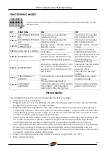
Страница 13: ...c friction M2 SW 3 indicates the operational sequence of the command Open Close SW 4 allows the set up of the function mode for automatic o semiautomatic SW 5 allows the insertion battering ram during the opening phase SW 6 allows selection of delaying the second in respect to the first shutter SW 7 allows selection of operating with 1 or 2 motors SW 8 allows adjustment of the mains for automatic ...

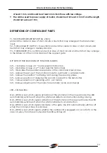
Страница 14: ... two leafs of the gate without the need of a limit switch Pedestrian input enables the controlling of the opening and closing of only one connected with M1 motor shutter of the gate Open Close input enables the sending of closing and opening commands of the gate according to the sequence that depends on the position of the dip switch SW 3 Activated photocell in the closing mode input the activatio...

Страница 15: ...ING Proceeds the operation of automatic learning of the shutter movements and bringing to automation the closing time The automatic learning phase is deactivated PROGRAMMING The programming of the central unit requires the following steps Manual opening of the gate Program SW 8 ON the blinking unit will emit a steady light to inform the user that the programming procedure has been started Press th...

Страница 16: ...tomatic closing is programmed 3 During the opening phase with SW 3 OFF and with SW 4 ON every Open Close command terminal 19 will be inactive whereas during the closing phase the two leaf movement is inverted with each impulse CONDOMINIUM MODE If the semi automatic functioning is activated with SW 3 OFF every Open Close command will cause the inversion of gate leaf movement both during the opening...

Отзывы: