background image

Chapter3. Installation 


Stack DVR2 Users Guide 

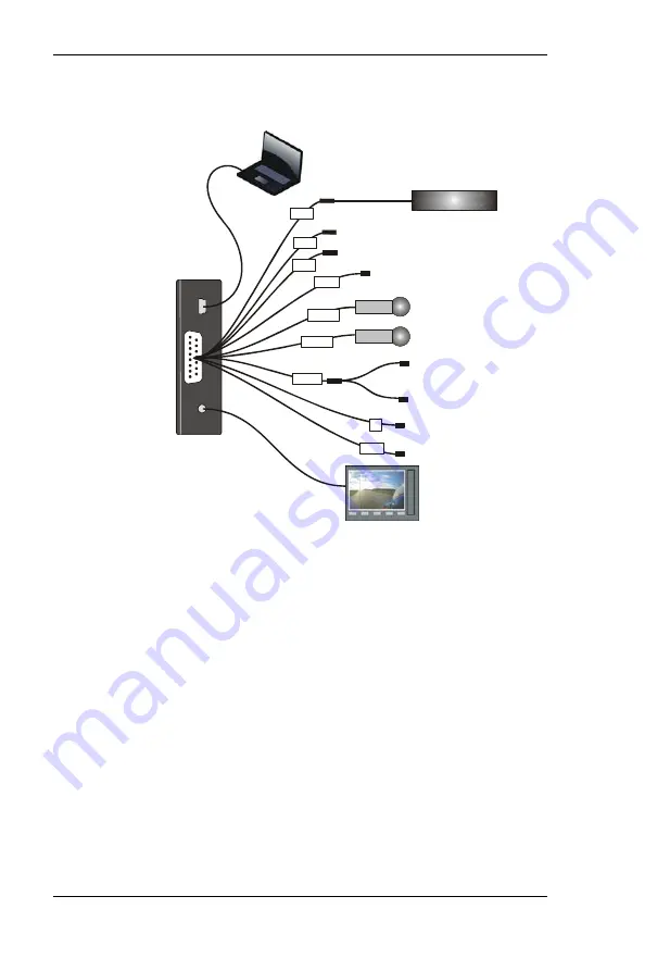
DVR2-130 Wiring 

Micro
USB

15-way
D Conn

4-way
Jack

Bullet Camera

Microphones

Record Switch

Record Switch

Recording Lamp

Power 9 to 20 volts

PC USB Port

Monitor

Power supply for mics etc

red

B

12V

C1

CTL

left

right

white

DL

Data Link In

C3

C2


Connect a camera to the 4-way CAM plug on the wiring 
harness. 

!


If you are using your own camera, you may need to obtain 
the optional CAM plug to BNC and Power lead (ST918106) 
from your Stack distributor. 

Connect the Record Switch and Recording Lamp lead to the 
CTL connector.  Extender cables are available from Stack’s 
dealers. 

The Recording Lamp output can be used to drive an input on 
some other equipment to indicate the DVR2 is recording.  
This is an open collector output and must not be used to drive 
more than 25mA max. 

Connect a permanent DC supply of between 9 and 20 volts 
(or 20 to 50volts for the High Voltage Option ST9399) to the 
Power (B+ and B-) connectors.  You must provide a 5 amp 

Содержание DVR2-130

Страница 1: ...Part No ST542103 004 DVR2 130 DVR2 240 DVR2 440 DVR2 540 Users Guide ...

Страница 2: ......

Страница 3: ...er Stack motor sport products these can be obtained from Stack or from your local Stack dealer Products available from Stack include Intelligent Tachometers Auxiliary Gauges Analogue and Digital Sensors Data Logging Systems Display and Logging Systems Radio Telemetry Systems Display and Analysis Software Video Overlay Systems Solid state Video Recorders Tyre Pressure Monitoring Systems Stack is a ...

Страница 4: ...o make a recording 13 To play a recording 16 Operation with a new Compact Flash Card 17 Formatting a Compact Flash Card 18 Deleting Files 18 Corrupted Compact Flash Cards 18 Chapter 5 Compact Flash Cards 20 Chapter 6 Configuration 21 PC Connection 21 System Information 23 Video Setup 24 Audio Setup 30 Tools PINCODE Authorisation 31 Chapter 7 Video and Data Systems 32 Synchronised Video Logger Syst...

Страница 5: ...09 41 DVR2 240 440 540 System Harness ST918101 42 Control Status Harness ST918105 42 DVR2 240 440 540 Input Harness ST918107 43 DVR2 240 440 540 Monitor Harness ST918114 42 DVR to VS Adapter Harness ST900144 44 Appendix C Upgrading the Firmware 44 Appendix D Service and Support 45 Stack Web site 45 Contacting your Dealer 45 Stack Contact Details 48 Index 49 ...

Страница 6: ......

Страница 7: ... using a standard media player application Recordings can be copied direct to DVD for playback on either a PC or a DVD player A data overlay feature is available so that date time and GPS Data may be stamped onto the recorded video Stack DVR2s feature a rugged machined aluminium housing specifically designed and manufactured to protect the unit in harsh and extreme environments The unit is compact...

Страница 8: ...up to four camera inputs higher bit rate options for broadcast quality recordings models offering completely sealed units to IP67 extended operating temperature ranges and extended recordings capacity Stack DVR2s provide superior high quality video recording in real time over a wide range of bit rates suitable for different applications up to 20 Mbps is available quality equivalent or better than ...

Страница 9: ...9 DVR2 Configuration Utility Software DVR2 2 4 5 The DVR2 240 440 540 are supplied with the following standard components Quantity Description 1 ST990063 DVR2 Module 1 ST918101 DVR2 System Harness red 1 ST918107 DVR2 Input Harness yellow 1 ST918114 DVR2 Audio Video Harness blue 1 ST918105Switch and Lamp Harness 1 ST920039 DVR2 Configuration Utility Software Optional Components DVR2s may be supplie...

Страница 10: ...y MPEG 2 compliant They may be played directly from the card by inserting it into a PC with a suitable Compact Flash card slot or adapter However better replay results are usually obtained by transferring the file to the PC s hard drive see page 15 Before Making a Recording Before a recording session clear the Compact Flash card so that maximum space is available Deleting files can cause the write...

Страница 11: ...delete files from the CF card that won t necessarily restore full performance due to file fragmentation The restore performance once a recording has been made transfer the files to your PC s hard drive and then perform a format Ensure any useful recordings have been archived before performing a format ...

Страница 12: ...the components which came with your system You may like to perform a dry run by connecting the components together to get a feel for how the final installation will be accomplished The DVR2 Module Status Lamp Flash Card Slot Card Eject Button Door Catch The Front Panel showing the Card Slot USB B 15 way D Conn AV Jack DVR2 130 Rear Panel showing the Connectors ...

Страница 13: ... A rigid mounting can be made to a suitable bracket using the six M3 tapped holes in its underside see Appendix A for dimensions Once a mounting position has been determined the components should be connected using the wiring harnesses supplied The figures below show the standard electrical connections to the unit If you are using the DVR2 with a Stack Video Overlay system an adapter harness is av...

Страница 14: ...ou may need to obtain the optional CAM plug to BNC and Power lead ST918106 from your Stack distributor Connect the Record Switch and Recording Lamp lead to the CTL connector Extender cables are available from Stack s dealers The Recording Lamp output can be used to drive an input on some other equipment to indicate the DVR2 is recording This is an open collector output and must not be used to driv...

Страница 15: ...2 1 mm power connector has been provided for powering microphones Note The regulated 12 volt power also supplies the cameras maximum total load is 1 0Amps If the current required is greater than 1 0A you must provide a separate power supply If audio recording is not required it may be disabled to extend the recording time see page 30 Connect a GPS receiver into the DL Data Link connector input for...

Страница 16: ...ave into the appropriately coloured connector on the rear panel of the DVR2 Input Harness yellow Starting from C1 connect a camera to each of the 4 way CAM plugs on the wiring harness If you are using your own camera you may need to obtain the optional CAM plug to BNC and Power lead ST918106 from your Stack distributor The following connections are optional If audio recording is required connect y...

Страница 17: ...upply of between 9 and 20 volts or 20 to 50volts for the High Voltage Option ST9399 to the Power B and B connectors You must provide a 5 amp fuse in the B connection to protect the DVR2 An independent switch can be added to isolate the module A permanent power supply is required to ensure that recording finishes cleanly when the Record Switch is turned off If the supply is obtained from a vehicle ...

Страница 18: ...se This harness allows direct connection between the DVR2 and a Stack VS VSR Module With this harness the signal from the camera is first directed to the VS VSR Module which overlays vehicle data on to the picture before that signal is passed to the DVR2 Connect the various components as described above with the addition of connecting the 15 way MIL connector to the VS VSR module see page 42 This ...

Страница 19: ...erted with its manufacturer s label facing downwards and the lip uppermost If there is resistance the card is probably upside down Attempting to insert the card incorrectly will damage the DVR2 and void the warranty Apply DC power and after about a 20 second delay while the system boots up the Status Lamp on the front panel will light showing the status of the unit If the Status Lamp shows static ...

Страница 20: ...econds on 1 5 seconds off With approximately 10 remaining the Status Lamp will flash for 0 3 seconds on 2 7 seconds off To stop recording open switch off the Record Switch The Status Lamp will revert to showing static green and the Recording Lamp will be extinguished Do NOT remove the CF card whilst recording is in progress The Compact Flash card may now be removed and placed into a PC with a suit...

Страница 21: ...ing red Unable to record Video and card not present or full or system fault PC Connected Flashing equally green red 0 5s red 0 5s green DVR2 is under external control of the Configuration Utility Recording 100 Memory 50 Remaining 10 Flashing green External Recording Lamp also illuminated Recording OK The longer the green flash the greater the memory remaining With a new card the Status Lamp will f...

Страница 22: ...Flash card contents My Computer Removable Drive DVR2 Files DVR2 video files are MPEG 2 compliant and filenames begin with STACK and have a MPG extension The files are given sequential numbers starting from zero eg STACK24 MPG With a standard Windows configuration they will be seen as media files see above To play simply double click the file and it will be displayed Due to the relatively slow read...

Страница 23: ...AT32 File System Before using a new Compact Flash card check its File System by inserting into a PC and displaying the card properties by right clicking the disk icon in My Computer If the Compact Flash card was supplied as FAT16 reformat to FAT32 using Windows XP or Vista s format utility to select the File System see Formatting a Compact Flash card below ...

Страница 24: ...de over time Only a reformat will restore the maximum write read speed of the Compact Flash card So once a recording has been made which you intend to keep transfer that file to your PC s hard drive and then perform a reformat of the removable card to keep it in top condition In summary to keep your Compact Flash card in good condition do not delete files Remove files for archiving and then reform...

Страница 25: ...ted from the DVR2 during a recording it is possible the card may become corrupted or the files could be incomplete In this case run Windows Scan Disk routine which will help recover any missing data To run Scan Disk right click on the Compact Flash card icon in My Computer and select Properties Select the Tools tab and under Error checking click Check Now The Check Disk dialog will now be shown Ch...

Страница 26: ...ly operate if formatted as FAT32 Check any new Compact Flash card before using with the DVR2 If supplied as FAT16 reformat to FAT32 For the highest quality recording it is essential that the Compact Flash card has a sustained write speed of 16 or faster If the card is too slow video will play back with missing frames This problem can be alleviated by recording at a lower video quality see page 30 ...

Страница 27: ...d return it to normal operation Alternatively you can upload the new configuration by clicking the Write Config button In both cases you MUST remove the USB cable for the DVR2 to accept the changes PC Connection Install the DVR Configuration Utility which can be found on the CD ROM supplied with the DVR2 system Once installed connect the USB cable to a USB port on the PC Run the DVR Configuration ...

Страница 28: ...sferred from the PC to the DVR2 The DVR Configuration Utility status will show Waiting for connection while the DVR reboots with the new configuration Factory Reset Clicking this button causes the DVR2 to reset back to its manufacturing default settings It should only be necessary to do this in the unlikely event that the DVR2 s internal set up has become corrupted Once you have clicked the Factor...

Страница 29: ...ers of the DVR2 and the DVR Configuration Utility software System Information Screen If a Compact Flash card is fitted this screen will show details of the card including an indication of the amount of space which has been used Click the Upgrade button to upgrade the firmware in the DVR2 see Appendix C ...

Страница 30: ... you to configure the amount of compression employed by the system The software shows an estimate of the record time at the bottom of the screen depending upon configuration Record Resolution Allows you to adjust the resolution of the recordings to those shown in the table below The software shows an estimate of the record time at the bottom of the screen depending upon resolution ...

Страница 31: ... at the Full D1 resolution Video Input Configures the system to either PAL or NTSC Video Source Configures the system to either Composite or S Video Only the Composite input is available on the DVR2 Video Bitrate This option is used to enable Constant or Variable Bit Rate support Variable Bit Rate is only available on the DVR2 440 540 Video File Index Counter Use this to reset the numeric index us...

Страница 32: ...list You may customise the selected overlay channel by entering your own text in the Channel Label and or Unit Label boxes You may also select a different Format or Units option using the dropdown boxes where available To reposition an overlay channel simply left click and drag the channel on the display grid to a new location To delete an overlay channel click on the desired channel in the displa...

Страница 33: ...r successful authorisation you may tick the Enable GPS checkbox at the bottom of the Video Overlay screen to enable the GPS channels in the lists The baud rate for your GPS receiver may also be set in the Video Overlay screen Camera Configuration New for 2010 models To configure the cameras select the Video Setup tab and then click the Camera button to access the camera configuration screen Camera...

Страница 34: ...drag any node on the rectangle to resize the crop area Click and drag within the rectangle to select a different part of the camera image Controls for Border Mirror and Flip are also located on the right of the configuration screen Full Screen Crop Window You may enlarge the input camera window for more precise positioning by clicking the appropriate Camera 1 Camera 2 etc buttons on the bottom lef...

Страница 35: ...rant button on the toolbar as below Quadrant Style Output To maximise a window first select the window by clicking it then click the maximise button on the toolbar Selecting more than one window by holding down the Ctrl button while clicking the windows will enable the alignment buttons on the toolbar If you are using Text Overlay you may click the Set as Overlay Background button to use the curre...

Страница 36: ...anced AGC tab options Select AGC Disabled to configure the recording levels individually for each stereo channel You can use Record Bitrate to set the amount of compression applied to the audio signal Set the Audio Input level to match your microphones Set the Audio Input to Microphone only if you need to turn on the microphone bias supply Uncheck Enable Audio if you do not want to record audio th...

Страница 37: ...R2 Users Guide 31 Tools PINCODE Authorisation The Tools tab allows you to authorise a PINCODE PINCODE Authorisation Screen Enter your supplied PINCODE exactly as it appears on your packing list then write the configuration to the DVR ...

Страница 38: ...tion includes a Stop Log command which will also stop the DVR2 recording Video Overlay Systems If the DVR2 is part of a data overlay system that does NOT include a recorder then the VS VSR will need to be configured with an action to start the DVR2 recording Automatic recording start control The recording status of the DVR2 is automatically controlled by the VS VSR module Shown is a test based on ...

Страница 39: ...tch such that either the VS VSR output or the DVR2 Record Switch can cause the DVR2 to start recording To stop the DVR2 recording both the VS VSR output and the DVR2 Record Switch must be off to stop recording Recording Lamp The DVR2 Recording Lamp output is directly connected to both the DVR2 Recording Lamp and the VS VSR Video Status Lamp When the DVR2 is recording both lamps will be illuminated...

Страница 40: ... that the system can detect that for instance the Engine Speed RPM has fallen to zero and will have sufficient time to stop the DVR2 from recording before power is removed from the Stack system Failure to stop the DVR2 from recording before the power is removed will cause up to the last 20 seconds of the video recording in progress to be lost ...

Страница 41: ...to obtain a plug in for your media player This can often be obtained via the Microsoft Update web site Video will not play back correctly on a DVD player Record Resolution is too low Increase Record Resolution to its highest setting Many DVD players will not work with low resolution video files Video Playback is jerky or hesitates The transfer rate from the Compact Flash card to the PC is not fast...

Страница 42: ...card Electrical Connectors DVR2 130 15w D 4w jack Micro USB DVR2 240 440 540 1 x 5w AS 2 x 9w AS Configuration Operating System Windows XP or Vista Connection Configuration uploaded from PC via USB cable Recording Media Recording Media Compact Flash Maximum Media size 16 Gbyte 32 Gbyte DVR2 440 540 Maximum File size 2 Gbyte Larger recordings are automatically fragmented into 2 Gbyte files with 0 5...

Страница 43: ...pression format MPEG 2 MP ML PS Resolutions supported See Table 1 CF Recording time at D1 resolution 9 to 136 minutes per Gbyte Quality bit rates DVR2 130 6 Fixed 1 2 4 5 6 8 Mbps DVR2 240 7 Fixed 1 2 4 5 6 8 10 Mbps DVR2 440 9 Fixed 1 2 4 5 6 8 10 12 15 Mbps also Variable Bit Rate DVR2 540 10 Fixed 1 2 4 5 6 8 10 12 15 20 Mbps also Variable Bit Rate Audio Channels 2 In 2 Out 0 to 40dB Analogue In...

Страница 44: ...k 50 G 15 ms Radiated emissions EN55024B CiSPR25 Radiated immunity 50 V m Conducted immunity DIN40839 Cat IV Specification is for the DVR2 only When combined with a CF card the specifications will be reduced to the lesser of the two Table 1 Resolution PAL NTSC Full D1 720 x 576 720 x 480 Medium 2 3 D1 480 x 576 480 x 480 Small 1 2 D1 352 x 576 352 x 480 Smallest SIF 352 x 288 352 x 240 Widescreen ...

Страница 45: ...Appendix A Mounting Template Stack DVR2 Users Guide 39 Appendix A Mounting Template Use the template on the next page for mounting the DVR2 Remember to leave room for card insertion and removal ...

Страница 46: ...Appendix A Mounting Template 40 Stack DVR2 Users Guide Compact Flash End M3 x 5mm deep 6 places 93mm 47 3mm 68 5mm 140 3mm View from above ...

Страница 47: ...hono Plug Cam B Cam B Vid1 I RI RO Gnd B Ext B VI 0V Mic R Mic L Out 1 Cam B Rx A 0V Vid1 I Ext B SW 1 Cam B Tx Mic R A 0V A 0V Mic L Cam B Cam B Ext B Ext B 1 2 3 4 1 2 3 4 6 7 8 9 10 11 12 13 14 15 1 2 3 4 5 VI 0V 1800 mm 200 mm 200 mm 200 mm 1500 mm 1500 mm DL Input MSS 4 Plug N C Ext B Rx Ext B 1 2 3 4 250 mm Video 2 In CAM Plug Cam B Cam B Vid2 I VI 0V 1 2 3 4 1800 mm Video 3 In CAM Plug Cam ...

Страница 48: ... Ext B Rx Ext B 1 2 3 4 Control Status Harness ST918105 Control MSS 4 Receptacle 1 2 3 4 RI RO B GND Record Lamp Record Switch 1 KOhm Resistor 200 mm DVR2 240 440 540 Monitor Harness ST918114 MONITOR USB Data Audio Left USB 0V VID Out Left Audio Out Phono Plug white USB A Plug AS 9 way blue Video Out Phono Plug yellow 1 2 3 4 5 7 8 9 USB Data USB V USB Data USB 0V USB Data USB V 1 2 3 4 1000 mm 10...

Страница 49: ...Mic R Phono plug Camera 1 CAM Plug Cam B VI 0V Vid I VI 0V 12v Power out 2 1 Power plug Cam B VI 0V 1 2 3 4 5 1 2 3 4 Audio 0V Audio 0V 6 7 8 9 Vid3 I Vid2 I A 0v Vid4 I Camera 4 CAM Plug Cam B VI 0V Vid I VI 0V 1 2 3 4 Camera 3 CAM Plug Cam B VI 0V Vid I VI 0V 1 2 3 4 Camera 2 CAM Plug Cam B VI 0V Vid I VI 0V 1 2 3 4 1800 mm 200 mm 200 mm 500 mm 1800 mm 1800 mm 1800 mm ...

Страница 50: ...VI 0V 1 2 3 4 Video In CAM Skt Cam B Cam B Vid I VI 0V 1 2 3 4 Control Status MSS 4 Skt SW 1 Out 1 Cam B Cam B 1 2 3 4 1750 mm 250 mm 250 mm 1250 mm Appendix C Upgrading the Firmware From time to time Stack may release upgrades to the firmware within your DVR2 These upgrades can be found on the Stack web site together with instructions detailing how to perform the upgrade We suggest that you visit...

Страница 51: ...ly the FAQ Page If you need a User Guide click on Manuals and Download Support Area You must enter some basic information for Stack s internal use to gain access to downloadable versions of our product manuals These give clear instructions on installation and correct operation of your Stack product as well as Troubleshooting sections If you still have questions please contact your Dealer Contactin...

Страница 52: ...ll be charged for all services and payment is required before we conduct the inspection On completion of the inspection you will be advised of any work and the costs involved in repairing the goods At this point you have the choice to proceed or terminate this service It is your responsibility to safely ship at your expense the goods to Stack It is also your responsibility to arrange for the safe ...

Страница 53: ...tion Assessment will be conducted We will then contact you to advise the next course of action and will quote on expected duration and cost of repairs where applicable 3 Once we have received your authorisation to proceed with the repair we will complete the work and request payment A full final test will be conducted before the goods are packed ready for shipping 4 Once we have confirmation that ...

Страница 54: ...itial inspection we will quote for the final cost and expected duration of the service and any repair work We will ask you for authorisation to complete the work and request payment If you choose not to proceed we will return the goods to you as we received them and you will only be charged for the initial inspection and return freight Harnesses and Sensors Where goods include harnesses and sensor...

Страница 55: ...ade 44 frequently asked questions 45 GPS Receiver Video Overlay Support 27 input harness 43 make a recording 13 monitor harness 42 mounting template 39 PC connection 21 PINCODE Authorisation 31 play a recording 16 read configuration 22 record bitrate 30 record quality 24 recording lamp 33 resolution 24 service and support 45 service enquiries 46 specifications 36 Stack contact details 48 Stack web...

Отзывы: