DocID027916 Rev 2
27/79
UM1902
Hardware layout and configuration
78
5.19 Motor
control
STM32746G-EVAL evaluation board supports both asynchronous and synchronous three-
phase brushless motor control via a 34-pin connector CN1, which provides all required
control and feedback signals to and from motor power-driving board.
The available signals on this connector are emergency stop, motor speed, 3 phases motor
current, bus voltage, heatsink temperature, coming from the motor driving board and 6
channels of PWM control signal, going to the motor driving circuit.
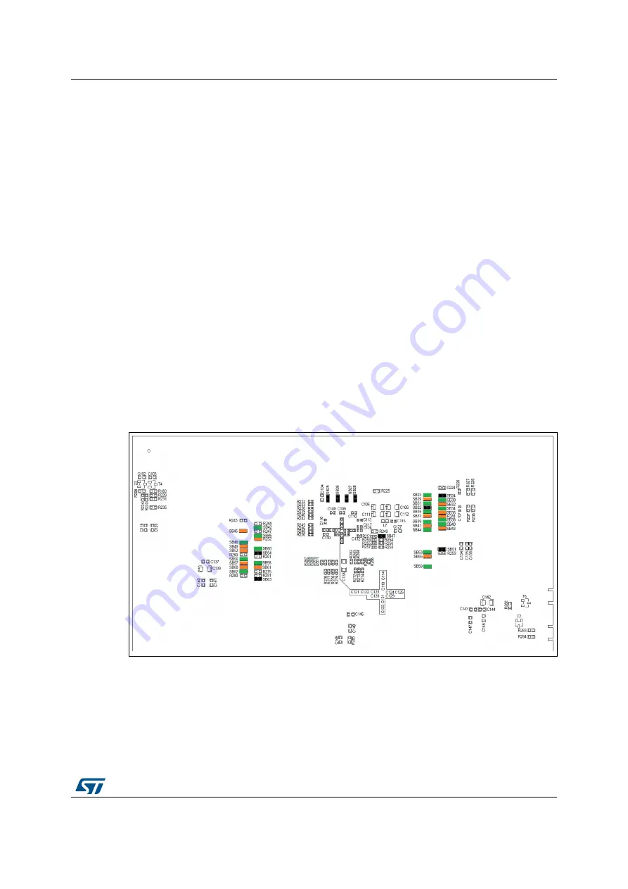
Some PCB reworks are needed for motor control application, to disconnect those
peripherals, which share I/Os with motor control connector and connect these I/Os to motor
control connector:
•
Open SB5, SB29, SB32, SB36, SB37, SB41, SB43, SB45, SB49, SB52, SB55, SB57,
SB60, SB61, Remove R95, R100, R241, R252, keep no jumper on JP4 (Pin2-3), keep
no jumper on JP8/JP21/JP22, keep no jumper on JP19 (Pin 2-3), keep CN4 and CN13
unconnected.
•
Close SB23, SB30, SB31, SB34, SB35, SB38, SB39, SB40, SB42, SB44, SB46, SB48,
SB50, SB53, SB56, SB58, SB59, SB62. Mount R14 with 0 ohm resistor.
PA4 and PA5 are DAC output; when using them for debugging purposes, keep CN4
unconnected and remove R126.
show that all the solder bridges and resistors to be removed, are
marked in orange, while the solder bridges to be closed, are marked in green.
Figure 6. STM32746G-EVAL evaluation board motor control PCB
reworks (Bottom side)


