


7
Application
Combination frame for modernising
an existing Vario 511 door station to
the current Vario 611 series, made
of sectional extruded aluminium
powder-coated or painted.
Electrical voltage
Mounting, installation and servicing
work on electrical devices may only
be performed by a suitably qualified
electrician.
Important installation instruc
tions
•
For each flush-mount housing
GU 513-… a Vario ad
apter
VA/GU 513-… an
d an
MR 611-1/3-… are required. The
hous
ing must be sealed a
gainst the
wall by the customer using all-round
acrylic grouting or a suitable sealant.
Depending on the mounting situa
-
ti
on, the service of a decorator or
plasterer may be required.
Scope of supply
• Co
mbination frame KR 613-…
•
Vario 511 key
• Fastening strips (2x
per letter flap)
• Cou
ntersunk screws M4 x 45
(2x per letter flap)
•
This product information
Mounting
Before starting renovation work,
disconnect the line rectifier of the
intercom from the mains.
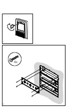
1
Unlock the mounting frame with
the silver Vario 511 key and open
up. Before disconnecting the termi
-
nals, inscribe them with
the terminal
names. Disconnect all connected
cores, loosen the 4 existing slotte
d
screws of the mounting frame. Pull
the
mounting frame off towards the
front. Release the 2 Phillips screws
holding each letter flap and take off
the flap.
English
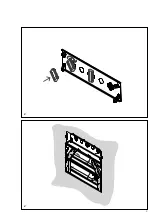
Pull the combination frame off
towards the front.
2
Insert the Va
rio adapter VA/
GU 513… into the flush m
ount
housing and screw into place.
3
Remove the combination fr
ame
from the module packaging. Centre
th
e combination termin
als turned
around 45° anticlockwise onto
the
relevant receptacles in the upper
a
dapter plate. Lock the combination
termi
nals into place clockwise with
a 45° turn. The terminal desi
gna-
tion must be capable of being read
vertically.
4
Insert the
fixing strips into
the
passthrough opening of the let
-
terbo
xes.
5
Insert the moun
ting frame into
the
combination frame. T
he sealing
film of the mounting frame mu
st
be located at the upper end. The
seal
ing profile of the c
ombination
frame must be open to the und
er-
neath. Press the combination frame
with the mounting frame
against the
wall and fasten using the provided
screws. The combination frame mu
st
rest flush against the wall.
6
Insert t
he letterbox and screw into
the fixing strips using the prov
ided
M4 x 45 screws.
7
Insert the Vario mo
dules.
8
Following function testing, seal
the combination frame to the wall
using
acrylic or a suitabl
e sealing
material. On the underneath of
the
frame, the opening of the periphera
l
sealing profile must be left free.
Accessories
Accessory fixing material for
installing another pass-through
flap in the KR 613-… combination
frame.
Sp
ecifications
Designation
Dimensions
(m
m) W x H x D
KR 613-
2
331 x 242 x 15
KR
613-3
331 x 354 x 15
KR 613-4
331 x 465 x 15
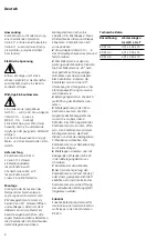
Application
Cadre combiné pour moderniser une
platine de rue Vario 511 et l’adapter
à la série actuelle Vario 611, en pro-
filés extrudés en aluminium, revêtus
à la poudre ou peints.
Tension électrique
L’installation, le montage et l’entre-
tien d’appareils électriques
ne
doivent être réalisés que par un spé-
cialiste en électricité.
Consignes de montage impor
tantes
• P
our chaque boîtier encastrable
GU 513-…, il faut un adaptate
ur
Vario VA/GU 513-…
et un
MR 611-1/3-…
•
L‘étanchéité par rap
port au mur
doit être réalisée sur site,
par un joint
acrylique périphérique ou un maté-
riau d‘étanchéité approprié.
•
En fonction des conditio
ns de
montage, des travaux de peinture
e
t de stuckage peuvent être néces-
saires.
Etendue de la fourniture
•
Cadre combiné KR 613-…
•
Clef Vario 511
•
Baguettes de fix
ation (2 par intro
-
du
ction du courrier)
• V
is à tête fraisée M4 x 45
(2 par introdu
ction du courrier)
• L
a présente informati
on produit
Montage
Avant de commencer la rénovation,
mettre le bloc d‘alimentation
de
l‘interphone à l‘état sans tension.
1
Ouvrir le cadre de montage avec
la clef argentée Vario 511 e
t le
relever. Avant de débrancher les
fils, les repérer par
les désignations
des
bornes. Débrancher tous les fils
raccordés, desserrer les 4 vis à tête
fendue présentes sur le cadr
e de
montage.
Français
Содержание KR 613-2
Страница 2: ...2 1 2 4x ...
Страница 3: ...3 4 3 ...
Страница 4: ...4 6 5 4x 2x ...
Страница 5: ...5 8 7 ...


