6
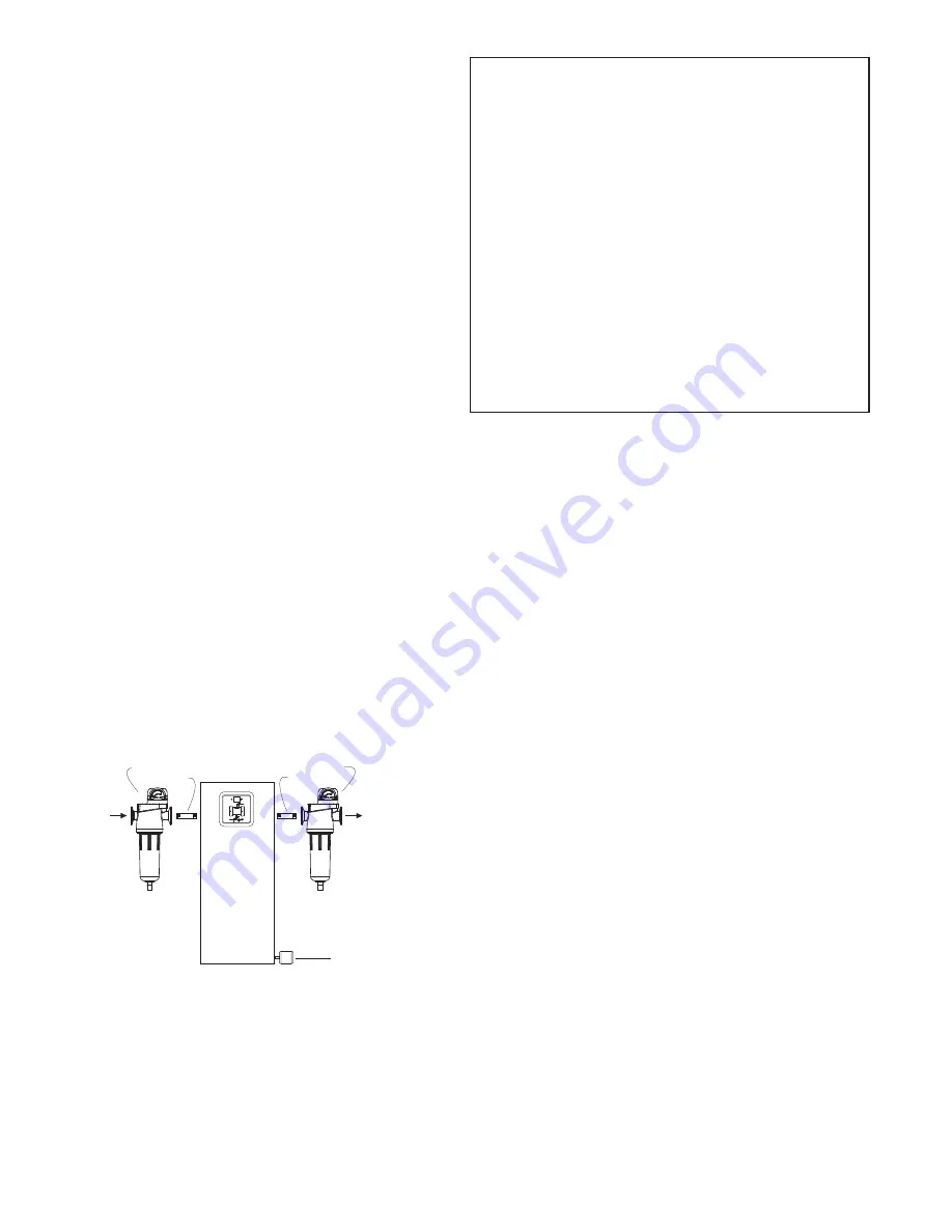
Figure 5
PREFILTER
AFTERFILTER
NIPPLE
NIPPLE
MUFFLER
From
Compressor
To Downstream
Air Lines
P1
P2
D.
Afterfilters
- To ensure downstream air purity (prevent
desiccant dust from traveling downstream) adequate
filtration down-stream of the dryer is required. De-
pending on the degree of purity you require from your
compressed air system, the following filters are recom-
mended:
1.
Air Line Filter
- Use as an afterfilter to remove desic-
cant fines and protect downstream components from
solid particles 1 micron and larger. Filters for finer
solid particle filtration are available.
2.
Oil Vapor Adsorber
- Use as an afterfilter to remove
oil vapor and its subsequent taste and odor and to
protect downstream components from solid particles
0.01 micron and larger.
NOTE:
By-pass lines and isolation valves are recom-
mended so that maintenance work can be performed
without shutting off the air supply.
IMPORTANT:
The compressed air supply inlet should be
periodically checked to ensure that equipment design
specifications are not exceeded. Normally the compressor
installation includes intercoolers, aftercoolers, separators,
receivers, or similar equipment which adequately pretreat
the compressed air supply in order to avoid excessively high
air temperatures and liquid slugging of down-stream equip-
ment.
3.4 PreFilter and AfterFilter Installation
If supplied, install Prefilter and Afterfilter.
NOTE:
When installing, hold bulkhead fitting on dryer with
wrench and thread filter on by hand.
A. Install prefilter (F04-HF-DG1) ahead (upstream) of dryer.
Use nipple supplied to connect filter to inlet port of dryer.
B. Install afterfilter (F04-PF-TG1) downstream of dryer. Use
nipple supplied to connect filter to outlet port of dryer.
NOTE:
Observe arrows on differential pressure gauge to
ensure proper flow direction through filter.
3.5 Wall-mounting
Four holes are provided in rear of cabinet. Attach cabinet
to wall using four (4) screws. User is responsible for select-
ing screws of the appropriate strength and ensuring the wall
mounting surface can safely support the weight of the dryer
(See Section 3.1).
3.6 Piping
Connect air line from compressor to inlet of prefilter or
dryer. Connect downstream air line to outlet of afterfilter or
dryer.
3.7 Electrical connection
Check to see that power supply to dryer is the same as the
power requirements indicated on the identification label.
Install plug into receptacle of proper voltage or hardwire to
pigtails and ground screw inside cabinet.
3.8 Muffler Installation
Install muffler (packaged separately inside dryer shipping
box) to fitting on side of cabinet.
3.9 Moisture Indicator Installation
Install the moisture indicator (shipped separately inside
of cabinet) directly into the pipe line anywhere in air/gas
system where moisture level is to be monitored. If indica-
tor is installed parallel to main line, make sure enough of a
restriction exists in main line to force adequate flow through
indicator.
3.10 Initial desiccant charge
The dryer is shipped complete with desiccant and ready to
operate after piping and electrical connections are made.
CUSTOMER ASSEMBLY
INSTRUCTIONS
These instructions MUST be followed prior to mounting of
dryer enclosure.
1. Connect prefilter and afterfilter to enclosure (if
applicable).
2. Mount dryer.
3. Connect to inlet, outlet, and purge connections. (see
NOTE)
NOTE:
If the equipment is to dry (or reactivate with) a gas
other than air, the outlets of the safety valve, reactivation
gas outlet line, blow down valves, etc. are to piped away
to a safe location (by purchaser). In piping away gas, do
not pipe upward without adequate arrangements to
prevent trapping condensation.
4. Install moisture indicator downstream of dryer outlet (if
applicable).


