5
2.5"
(FROM FRONT OF HOOD)
TYPICAL HANGER ROD
BRACKET ISOMETRIC
HOOD
2.25"
TOP OF
2.5
HANGER BRACKET
OFFSET 1/2" FROM
EDGE OF HOOD
Ø 17/32"
PRE DRILLED HOLE,
ACCEPTS UP TO
1/2" Ø ROD
HANGER ROD
HANGER ROD NUT
Standard
Dynaflow MJ hood Specification
The unit casing shall be a minimum 18 GA. stainless steel, with No. 4 finish on all exposed surfaces. The hood shall include UL/ULC
listed grease filters mounted in an integral stainless steel rack inclined at 45 degrees. The filter rack shall include a full length stainless
steel grease gutter and grease cup.
The MJ blowers provides ceiling return air to the MJ plenum which discharges out the bottom of the plenum through a s/s perforated
plate along the length of the MJ plenum. The return air is directed through the MJ plenum towards the appliances. MJ blower(s) mounted
on top of the plenum shall be complete with adjustable Triacs, washable filters and wired to a common J-box on top of the hood. A
fusible link fire damper is located below each MJ blower.
The hood shall have ______ incandescent/fluorescent/recessed/incandescent/LED lights evenly spaced along the length of the hood.
Optional Sideflow right and/or left MJ blower assemblies are available.
Dynaflow Installation
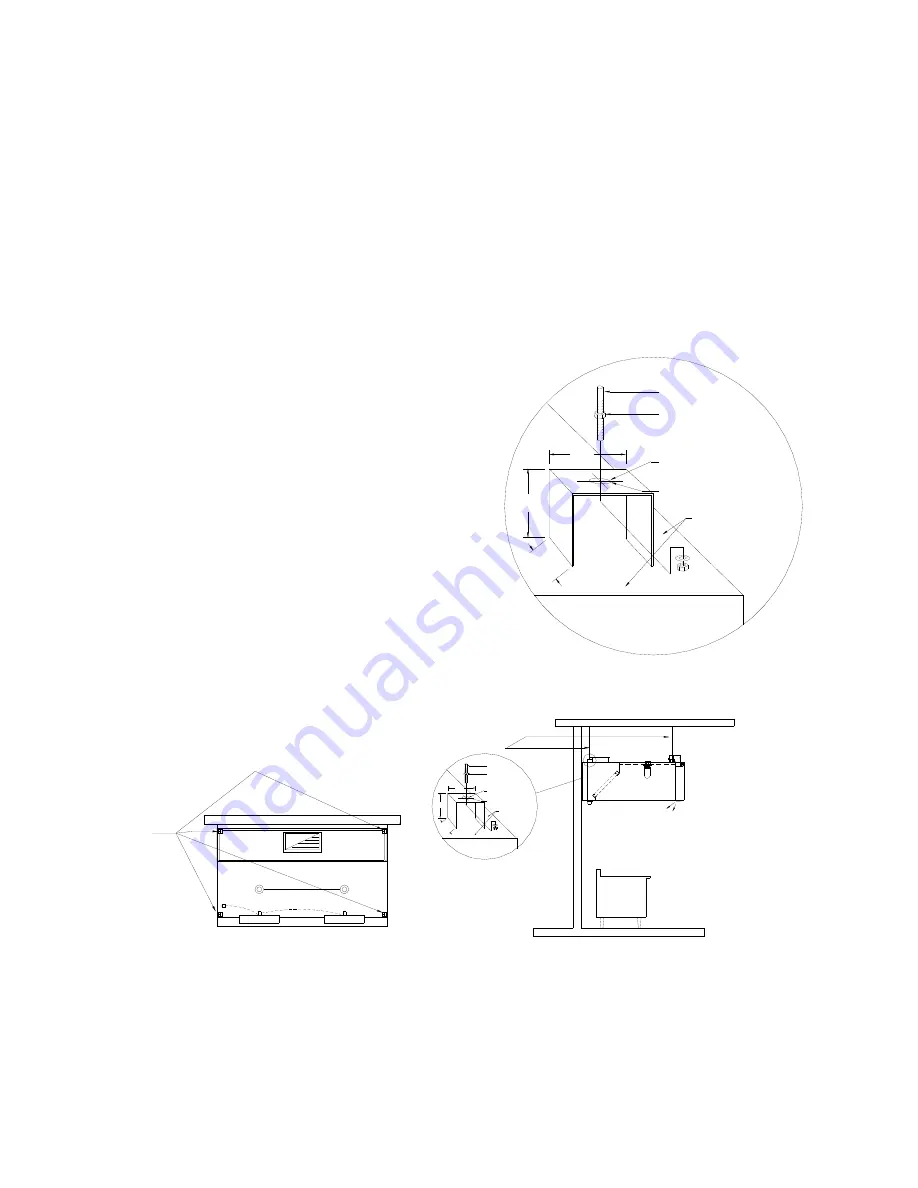
The Dynaflow hoods are hung from 4 or more hanging brackets
(depending on the model) mounted on top of the hoods as
indicated on the engineering drawings. The engineering
drawings indicate number and location of the hanger bracket.
All hanger brackets shown on the Spring Air Systems
drawings must be used to support the hood. Spring Air
Systems assumes no responsibility for the field installation
of the any hood.
A typical schematic is shown to the right with recommend
method on installing the hanger rods to the hanger brackets.
The size of the hanger rods, washers and nuts must be
determined by a structural engineer based on hood weight and
site conditions. All hood weight is shown on the Spring Air
Systems section view drawing. The hanger rods must be size to
safely hold the weight of the hood from the structure above.
The structure above must be designed to hold the weight of the
hood. Structural engineers will be required to determine what is
acceptable. The hanger bracket diagram indicates how the rod
is attached to the hood. All hanger rods must be installed
perpendicular to the roof of the hood.
MJ BLOWER
MJ BLOWER
FOUR (4)HANGER
BRACKET LOCATION
MJ DYNAFLOW PLAN VIEW
APPLIANCE
2.5"
(FROM FRONT OF HOOD)
TYPICAL HANGER ROD
BRACKET ISOMETRIC
HOOD
2.25"
TOP OF
2.5
HANGER BRACKET
OFFSET 1/2" FROM
EDGE OF HOOD
Ø 17/32"
PRE DRILLED HOLE,
ACCEPTS UP TO
1/2" Ø ROD
HANGER ROD
HANGER ROD NUT
HANGER ROD BY INSTALLER
MJ DYNAFLOW HANGER BRACKET SECTION VIEW
Wall mounted Dynaflow model FN-B-MJ Hood in Plan and Section View showing hanger rod locations.
Figure 7
Hanger Rod Schematic
Figure 6
Содержание Dynaflow
Страница 23: ...21 Chart No 4...


