background image

15

98-05238 R1 EN-US

HOME

OVER

VIE

W

SE

TUP 

POWER

APPENDIX

FULL SCREEN

INTR

ODUC

TION

GUID

ANCE

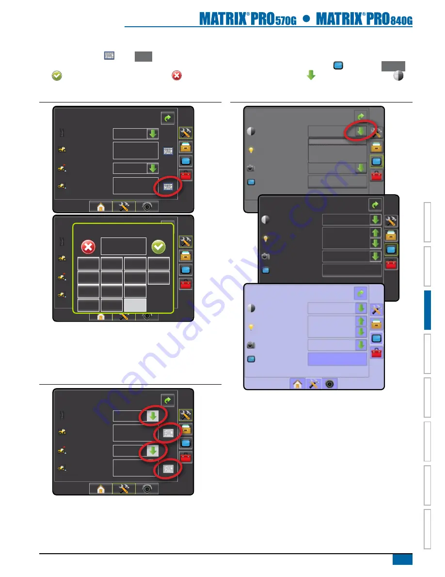
Keyboard Entry Screen

Press the KEYPAD icon 

. Press 

 Clear 

 to erase the existing 

value. Use the numeric keypad to enter a value. Press the ACCEPT 

icon 

 to save the settings or the CANCEL icon 

 to leave the 

keypad without saving.

Figure 3-6: Example of Keyboard

Config-> Vehicle

12.50 ft

0.00 ft

Front wheel

backward

Vehicle Type

Ant Height

dir to boom

dist to boom


Config-> Vehicle

12.50 ft

0.00 ft

Front wheel

backward

Vehicle Type

Ant Height

dir to boom

dist to boom

dist to boom (ft)

1

2

3

0.00

Clear

4

5

6

<--

7

8

9

0

.

+/-

Unavailable Options When Job is Activate

When a job is active some setup options are unavailable. See 

the Unit Setup Mode Menu Structure Chart for indication of which 

options are not accessible.

Figure 3-7: Example of Unavailable Options

Config-> Vehicle

12.50 ft

0.00 ft

Front wheel

backward

Vehicle Type

Ant Height

dir to boom

dist to boom

Light or Dark Console Screen

The console is available in three color schemes. From the Unit Setup 

Bottom Key, press CONSOLE side tab   and enter the 

 Display 


options. Press DOWN arrow   to access the Color Scheme 


options to select color mode.

Figure 3-8: Color Scheme

Console->display

Color Scheme

brightness

Screenshot

Calibrate

Style 1

Enabled

Start

Style 1
Style 2
Style 3

Console->display

Colour Scheme

brightness

Screenshot

Calibrate

Enabled

Style 2

40%

Start

Console->display

Colour Scheme

brightness

Screenshot

Calibrate

Enabled

Style 3

40%

Start

Содержание TeeJet Matrix Pro 570G

Страница 1: ...VOYAGER 570g U s er M A N U A L U s er M anual...

Страница 2: ...Home Screen 12 Simple Mode 12 Advanced Mode 12 Basic Screen Use 12 Bottom Tab Keys 12 Warnings and Information Pop ups 13 Setup Screens 13 Side Tab Keys in Unit Setup 13 Setup Option Information 14 D...

Страница 3: ...r 6 SYSTEM SETUP 32 Overview 32 Unit Setup Mode Menu Structure 33 Setup Option Information 34 Drop Down Menu Selections 34 Keyboard Entry Screen 34 Unavailable Options When Job is Active 34 Configurat...

Страница 4: ...rate Sensor 51 Offset Adjustment 52 Tilt 53 Tilt Correction Unavailable 53 Enable Disable Tilt 53 Field Level 54 LED Brightness 55 Display Mode 56 LED Spacing 56 GPS 57 GPS Type 57 GPS Port 57 Externa...

Страница 5: ...ess 71 Screenshot 71 Capture a Screenshot 72 Touch Screen Calibration 72 Cultural 73 Units 73 Language 73 Time Zone 74 Sound 74 About 74 TOOLS 75 Calculator 76 Units Converter 76 Set Units 77 Select V...

Страница 6: ...egree 96 Curved AB Guidelines 97 Marking A and B Points 97 A Nudge Feature 98 Next Curved Guideline Feature 99 Circle Pivot Guidelines 99 Marking A and B Points 99 A Nudge Feature 100 Next Guideline F...

Страница 7: ...ADVISED OF SUCH DAMAGES ARISING FROM TEEJET TECHNOLOGIES SOFTWARE Safety Information TeeJet Technologies is not responsible for damage or physical harm caused by failure to adhere to the following sa...

Страница 8: ...ight readable screen in either 5 7 14 5 cm or 8 4 21 3 cm size Product upgrades include FieldPilot auto steering can perform on straight or contour paths UniPilot assisted steering can perform on stra...

Страница 9: ...k on when changing or attaching equipment to the Matrix Pro system Cleaning suggestions Matrix consoles should be cleaned with mild cleaners such as glass cleaner and a soft cloth Take care not to rub...

Страница 10: ...wer Button USB Port with Rubber Cover Standard RAM Bracket Bright Touch Screen Home Button Zoom In Out Buttons Rubber Connector Covers GPS Antenna Connection Integrated RAM Mount Speaker Speed Signal...

Страница 11: ...x Pro a benefit of a single in cab console FieldPilot FieldPilot automatic steering drives a vehicle with tremendous repeatable accuracy in both straight and curved patterns by tapping directly into t...

Страница 12: ...is mounted 12 feet 3 6 meters above the ground a 10 side slope can cause 2 feet 0 6 meter of position error The TeeJet Tilt Gyro Compensation Module corrects GPS position errors caused by side slope c...

Страница 13: ...ecting to different consoles requires different adapters and calibrations If connecting to TeeJet consoles please use speed adapter 45 20042 enter calibration 914 1000 in Europe for 8xx series in RAD...

Страница 14: ...er 45 08101 CAN Terminator 16 00022 RealView Camera 78 08067 Module 4 Channel Video CAN 78 08068 Video Selector Module 8 Channel Video CAN 45 05786 20 6m 45 05787 30 9m Antenna Cable 78 50187 Optional...

Страница 15: ...rness 45 07716 DC xx xx 78 08075 Steering Control Module SCM 45 07703 SCM Power In Out 45 10103 Harness Steering A B 78 08072 Voltage Regulator 45 07708 SCM Harness 32 04020 Optional Footswitch 32 040...

Страница 16: ...t 45 10103 Harness Steering A B 78 08072 Voltage Regulator 45 07708 SCM Harness 32 04020 Optional Footswitch 32 04040 Remote Engage Disengage Switch 91 07011 Steering Wheel Switch Kit 45 08117 CAN Ext...

Страница 17: ...ate Controller Console Harness Rate Controller Remote ABSC Status Switch Connection Valves 16 00022 RealView Camera 78 08067 Module 4 Channel Video CAN 45 05786 20 6m 45 05787 30 9m Antenna Cable 78 5...

Страница 18: ...Sequence The console takes approximately 40 seconds to power up During this time a series of screen including the TeeJet Technologies logo a globe an hourglass and an information screen will be displ...

Страница 19: ...or setup chapter for details Simple Mode In simple mode only one job will be available at a time Only bounded and applied area are displayed on the home screen Only the current job is available for sa...

Страница 20: ...Screens Side Tab Keys in Unit Setup Four side tabs on the Unit Setup screen access setup options for Vehicle Implement Configuration Vehicle Vehicle Type Antenna Height Direction to Boom Distance to B...

Страница 21: ...the illuminated LED s can be customized Input the desired spacing as required or individual preference LED Spacing Drop Down Menu Selections Press DOWN arrow to access the list of options Use the UP D...

Страница 22: ...When a job is active some setup options are unavailable See the Unit Setup Mode Menu Structure Chart for indication of which options are not accessible Figure 3 7 Example of Unavailable Options Config...

Страница 23: ...d Volume About System Information Save System Info Tools page 75 Job Extras Calculator Units Converter Configuration page 35 Job Vehicle Vehicle Type Antenna Height Direction to Boom Distance to Boom...

Страница 24: ...n displayed in the application area 6 0 mph 7 6 ac 0 0 Field View Guidance creates a computer generated image of the vehicle position and application area from an aerial perspective 6 0 mph 0 ac Mark...

Страница 25: ...s can be accessed by pressing the icon on the status bar GPS Status displays information regarding data rates number of satellites in view and satellite quality and ID Guidance Mode Status displays in...

Страница 26: ...tab to return to the main Console screen Figure 3 13 Cultural Options Console Settings Display Cultural Sound About Console Cultural Units US Language Time Zone English US UTC GPS 1 Press CONFIGURATIO...

Страница 27: ...tween guidelines Spray Width establishes the width of each boom section for a total spray width Overlap determines the amount of overlap allowed Delay On establishes the timing for the boom section va...

Страница 28: ...g installation manual NOTE An update of your SCM software will also be required when updating an existing Matrix console to Matrix Pro 1 Press CONFIGURATION side tab 2 Press AutoSteer 3 Select On enab...

Страница 29: ...ing in Reports and use with Fieldware Link is not available Figure 4 1 Simple Mode Home Screen 12 14 10 3 52 AM Do you want to start a new job data or continue last job Starting a new job will clear t...

Страница 30: ...or continuing a job Figure 4 3 GPS Not Available 12 14 10 3 52 AM Must have valid GPS signal before starting job Please wait New Job Continue Figure 4 4 Home Screen with Acquired GPS 12 14 10 3 52 AM...

Страница 31: ...New Job Continue 12 14 10 3 52 AM Do you want to start a new job data or continue last job Starting a new job will clear the previous job data New Job Continue Starting new job will delete the previo...

Страница 32: ...s HOME bottom tab 3 Press Close Job 4 Select Yes to create a report of the last job No to return to the Home screen without saving Figure 4 10 Close Job and Save Reports 12 14 10 3 52 AM Do you want t...

Страница 33: ...4 10 3 52 AM Must have valid GPS signal before starting job Please wait New Job Start Job Figure 4 12 Home Screen with Acquired GPS 4 4 11 6 38 AM Job Client Mr Nelson New Job Field Nelson Plot 23 Far...

Страница 34: ...sest to the vehicle s location With GPS acquired the job pick list will be updated every ten seconds During this update the list of jobs is sorted by distance and the closest two jobs are displayed on...

Страница 35: ...on the current job To create a report of the job 1 Insert a USB drive into the USB port of the console 2 Press HOME bottom tab 3 Press Close Job 4 Select Yes to create a report of the last job No to...

Страница 36: ...a View one 1 of up to eight 8 camera inputs can be selected to change the view of the video input Split Camera View one 1 of two 2 sets of four 4 camera inputs A B C D or E F G H can be selected to di...

Страница 37: ...en of that port s screen quarter Figure 5 3 Inactive Camera Ports Single Camera Selection One 1 of up to eight 8 camera views can be activated in RealView Guidance if a Video Selection Module VSM is a...

Страница 38: ...le in RealView Guidance if a Video Selection Module VSM is attached When an eight 8 channel VSM is on the system up to eight 8 cameras can be installed When a four 4 channel VSM is on the system up to...

Страница 39: ...ead Valve Test Valve Diagnostics Steering Wheel Sensor Steering Angle Sensor Tilt Configuration Lightbar Brightness Mode LED Spacing GPS GPS Type GPS Port GPS Information Video Configuration Data Mana...

Страница 40: ...nd Volume About System Information Save System Info Tools page 75 Job Extras Calculator Units Converter Configuration page 35 Job Vehicle Vehicle Type Antenna Height Direction to Boom Distance to Boom...

Страница 41: ...hicle 12 50 ft 0 00 ft Backward Vehicle Type Ant Height Dir to Boom Dist to Boom Front Wheel Front Wheel Articulated Tracked Config Implement Num Sections Spray Width Guidance Width 75 00 ft 75 00 ft...

Страница 42: ...rt as well as to view GPS status information Video used to set up individual cameras Figure 6 6 Configuration Options Configuration Vehicle Implement AutoSteer Tilt Lightbar GPS Video Vehicle Setup Ve...

Страница 43: ...ckward Vehicle Type Ant Height Dir to Boom Dist to Boom Antenna Height ft 1 2 3 12 50 Clear 4 5 6 7 8 9 0 Direction to Boom Direction to Boom sets whether the boom is located behind or in front of the...

Страница 44: ...ment AutoSteer Tilt Lightbar GPS Video Config Implement Num Sections Spray Width Guidance Width 60 00 ft 12 00 ft 1 Guidance Width Guidance Width establishes the width between the guidelines Range is...

Страница 45: ...to select the number of available boom sections Guidance Width used to enter the width between the guidelines Spray Width used to enter the width of each implement section Overlap used to select the...

Страница 46: ...tions Spray Width Guidance Width 60 00 ft 180 00 ft 15 Guidance Width ft 1 2 3 60 00 Clear 4 5 6 7 8 9 0 Spray Width Spray width establishes the width of each implement section When facing forward boo...

Страница 47: ...hen entering a non applied area increase the Delay On setting Range is 0 0 10 0 seconds 1 Press the KEYPAD icon 2 Use the entry screen to establish the delay on time Figure 6 17 Delay On Config Implem...

Страница 48: ...Steering Settings used to establish Coarse Adjustment Fine Adjustment Deadband and Lookahead Valve Test used to verify if steering is directed correctly Valve Diagnostics used to test the valves to se...

Страница 49: ...ring valve Frequency used to select the valve frequency used to drive the steering valve Minimum Duty Cycle Left and Right used to set the minimum amount of drive required to begin steering the vehicl...

Страница 50: ...ortional For valves manufactured by sources other than TeeJet Technologies please refer to manufacturer s specifications for appropriate valve frequency Minimum Maximum Duty Cycle Tests Minimum Duty C...

Страница 51: ...t the amount of drive to 25 0 Cycle test is not necessary 1 Press the KEYPAD icon 2 While the vehicle is moving in a slow forward straight line motion between 1 0 mph and 8 0 mph 1 5 13 0 km h 0 4 3 6...

Страница 52: ...ot the UniPilot will move the steering wheel very quickly Keep loose clothing hair and hands away from the steering wheel while preforming this test 5 When the wheels are all the way to the right or l...

Страница 53: ...s On Config AutoSteer Steering Setting Coarse Adjustment Fine Adjustment Deadband Lookahead 1 25 0 4 0 s 25 0 Coarse Steering Adjustment Coarse Steering Adjustment adjusts how aggressively the vehicle...

Страница 54: ...est The Valve Test verifies if steering is directed correctly It can also be used to test the amount of time to steer the wheels from full left to full right lock to lock for non proportional valves F...

Страница 55: ...ust the valve oil flow as needed and repeat test as needed Figure 6 37 Valve Test Config AutoSteer Enabled Valve Setup Steering Settings Valve Test Valve Diagnostics Options Angle Sensor On Config Aut...

Страница 56: ...unction Vehicle turns left Left and right connections to valve are reversed Steering Valve With Master Solenoid 1 Select Valve Diagnostics 2 Activate the Master check box 3 Activate the Left or Right...

Страница 57: ...alve Setup Steering Settings Valve Test Valve Diagnostics Angle Sensor Options On Config AutoSteer Options Steering Wheel Sensor Magnetic Magnetic Pressure Angle Sensor Angle Sensor is used to establi...

Страница 58: ...0 mph 1 5 13 0 km hr 0 4 3 6 m s 1 Select Calibrate Sensor 2 Slowly move the vehicle in a slow forward motion so the center two calibration boxes fill to 100 3 While still moving slowly turn to the r...

Страница 59: ...ustment 3 Engage assisted auto steering guidance on established straight AB guideline 4 While the vehicle is moving in a slow forward straight line motion at typlical operating speed on the establishe...

Страница 60: ...figuration screen NOTE If FieldPilot or UniPilot is being used tilt correction is built into the SCM NOTE Antenna Height must be entered prior to Tilt Calibration Figure 6 44 Tilt Configuration Vehicl...

Страница 61: ...vailable 5 Get out of the vehicle to mark on the ground the exact position of the vehicle use paint sticks or something similar 6 Turn the vehicle 180 degrees and reposition the vehicle in exactly the...

Страница 62: ...e swath or vehicle LED Spacing used to set the distance illustrated by the illuminated LEDs Press RETURN arrow or CONFIGURATION side tab to return to the main Configuration screen Figure 6 48 Lightbar...

Страница 63: ...bar Lights illuminated on the right of the Lightbar require a steering adjustment to the left Lights illuminated on the left of the Lightbar require a steering adjustment to the right Vehicle Lightbar...

Страница 64: ...nformation Internal GPS DGPS GPS Type GPS Type customizes the system to accept GPS source or DGPS source transmissions GLONASS is only available with a compatible receiver 1 Press DOWN arrow to access...

Страница 65: ...lites in view minimum of 4 are required for DGPS HDOP a measure of satellite geometry strength in the horizontal plane A HDOP value of less than 2 is preferred PRN the current DGPS satellite ID GGA Qu...

Страница 66: ...s 4 Press RETURN arrow or CONFIGURATION side tab to return to the main Configuration screen Figure 6 57 Video Configuration Vehicle Implement AutoSteer Tilt Lightbar GPS Video Config Video Video Setup...

Страница 67: ...the Matrix Pro 840G no setup options will be available Figure 6 61 Video w Single Camera Config Video There are currently no setting for the attached camera Four Channel VSM When a four 4 channel VSM...

Страница 68: ...mode or advanced job mode Figure 6 64 Data Management Options Data Manage Data Transfer Options Reports Manage Data When in advanced job mode the Manage Data screen allows the duplicating of a selecte...

Страница 69: ...appropriate check box es Guideline Data Boundary Data Applied Data 4 Press Copy 5 Enter a new job name using the on screen keyboard Figure 6 67 Duplicate Job Data Data Management Internal Storage Hea...

Страница 70: ...Herbicide Yes No Transfer When in advanced job mode the transfer screen allows the exporting or importing of selected jobs to or from a USB drive as well as deleting jobs Jobs exported to a USB storag...

Страница 71: ...rts USB Storage Export job data from internal storage to USB storage 1 Insert a USB drive into the console 2 Under Internal Storage select the job name to be exported 3 Press RIGHT arrow to export the...

Страница 72: ...ive Moving job data please wait Data Transfer Internal Storage USB Storage Field 1 Test Drive Data Transfer Internal Storage USB Storage Field 1 Test Drive Delete Job Data Delete job data from interna...

Страница 73: ...ENT side tab 2 Press Reports 3 Insert USB drive into the console 4 Select the job to be saved 5 Select PDF PDF report for print KML KML Google Earth Map SHP SHP ESRI shape data ALL PDF all available f...

Страница 74: ...Options If Advanced Job Mode is selected in the Options page any stored job can be reported 1 Insert a USB drive into the console 2 Under Internal Storage select the job name to be reported 3 Press t...

Страница 75: ...d XML files are processed by web browsers Like HTML KML has a tag based structure with names and attributes used for specific display purposes Thus Google Earth acts as a browser of KML files Please v...

Страница 76: ...screen All saved jobs can be saved in Reports With Fieldware Link a user can input client farm and field data as well as duplicate edit jobs for reuse of boundaries and guidelines 5 Changing job mode...

Страница 77: ...volume level of the audio speaker About used to display the system software version as well as the software versions of modules connected to the CAN bus Figure 6 82 Console Options Console Settings D...

Страница 78: ...settings above 50 may cause a High Temperature Warning The console will automatically dim the screen to reduce the console temperature Figure 6 85 Brightness Console Display Color Scheme Brightness S...

Страница 79: ...ed to activate a touch screen calibration 1 Select Start 2 Begin touch screen calibration Press Yes to perform touch screen calibration No to return to the display options screen 3 Press series of 5 c...

Страница 80: ...required for Assisted Auto Steering and Tilt Sensor Operation as well as proper BoomPilot operation Figure 6 90 Units Console Cultural Units Language Time Zone English US UTC US Metric US Language La...

Страница 81: ...ole Sound Volume 50 About About Save screen displays the system software version as well as the software versions of modules connected to the CAN bus To aid when troubleshooting problems in the field...

Страница 82: ...nit converter The unit converter calculates various measurements based on area length or volume 1 Press UNIT SETUP bottom tab 2 Press TOOLS side tab 3 Press Extras 4 Select from Calculator used to per...

Страница 83: ...5 2 9 6 3 Clear All x2 1 x Units Converter The units converter is an on screen option to performing unit conversions for area length and volume 1 Press CONSOLE side tab 2 Press Units Converter 3 Pres...

Страница 84: ...m To acres acres hectares square meters hectares 0 40469 1 Area Figure 6 99 Set To Units Area Converter Tools Extras Units Converter From To acres hectares acres hectares square meters 0 40469 1 Area...

Страница 85: ...guidance screens assist in keeping the user informed Vehicle View Guidance creates a computer generated image of the vehicle position displayed in the application area 6 0 mph 7 6 ac 0 0 Field View Gu...

Страница 86: ...ion area and determines no apply zones Boundary is established to the outside of an applied pass Grayed GPS is unavailable Finish Boundary Finalizes boundary process Boundaries can also be closed by t...

Страница 87: ...er when the vehicle is to the right of the AB baseline or a negative number when the vehicle is to the left of the AB baseline Heading Displays the course of travel based clockwise from a north base l...

Страница 88: ...traight AB Guidance Curved AB Guidance Circle Pivot Guidance Last Pass Guidance NextRow No icon No Guidance Bounded Area Status Outside Boundary Currently traveling outside bounded area Inside Boundar...

Страница 89: ...te 5 Hz VTG Rate 5 Hz Num Sats 10 HDOP 1 PRN 135 GGA Quality 2 Receiver 1 Guidance Mode Status Guidance Mode Status displays information regarding the pattern of guidance name of the current guideline...

Страница 90: ...tus of the assisted auto steering system 1 Press AUTOSTEER STATUS icon to view the assisted auto steering status Figure 7 7 Assisted Auto Steering Status 13 7 2 mph Mark A 13 7 2 mph Mark A AutoSteer...

Страница 91: ...eft or right section of the guidance bar to change the selectable job information Figure 7 9 Guidance Screen Options RealView Guidance Field View Guidance Vehicle View Guidance Unit Setup Home Job Scr...

Страница 92: ...lines Points markers for established points Red Point Return to Point Blue Point Mark A Green Point Mark B Horizon Compass general heading can be displayed on horizon when zoomed in Coverage Area illu...

Страница 93: ...options On Screen Guidance Guidelines Orange active guidance line Black boundary line Points markers for established points Red Point Return to Point Blue Point Mark A Green Point Mark B Coverage Are...

Страница 94: ...two sets of four camera inputs A B C D or E F G H can be selected to divide the screen into four separate video feeds From this screen one can enter guidance over video and steering angle modes Figur...

Страница 95: ...raight line guidance based on A and B reference points The original A and B points are used to calculate all other parallel guidelines NOTE Offset to adjacent guidelines will be calculated using the g...

Страница 96: ...et to adjacent guidelines will be calculated using the guidance width which is encoded in Unit Setup in the Implement menu HINT Start on the longest curve of the field While working in a bounded area...

Страница 97: ...ct application in a center pivot field while being guided along a circular guideline that matches a center pivot irrigation system radius NOTE Offset to adjacent guidelines will be calculated using th...

Страница 98: ...ne and establish adjacent pass based on that guideline NOTE If a boundary is established but no application occurred during the boundary process guidance will not initiate 1 Press NAVIGATION AND GUIDA...

Страница 99: ...in the NextRow guidance is turned off NOTE Offset to adjacent guidelines will be calculated using the guidance width which is encoded in Unit Setup in the Implement menu 1 Press NAVIGATION AND GUIDANC...

Страница 100: ...ines or points from the console To delete established saved data from the console please refer to the Data Management section under Unit Setup 1 Press NAVIGATION AND GUIDANCE OPTIONS icon to display n...

Страница 101: ...2 Select CURVED LOOKAHEAD icon The pointer will be visible on the navigation screen Figure 7 22 Curved Lookahead 13 7 2 mph Mark A To remove the Curved Lookahead guideline 1 Press NAVIGATION AND GUID...

Страница 102: ...his guideline Yes No 1 14 PM 7 2 mph 0 0 Enter Name 1 5 9 2 6 0 3 7 4 8 q Caps Alt t f v o k Shift w a z y g b p l e s x u h n r d c i j m Figure 7 26 Follow Guidance 1 18 PM 7 2 mph 0 0 A Nudge Featu...

Страница 103: ...ht AB Name Stream Edge Total 4 A Azimuth Degree An azimuth is defined as a horizontal angle measured clockwise from a north base line When using an azimuth the point from which the azimuth originates...

Страница 104: ...navigation options 3 While the vehicle is in motion press MARK A icon A 4 Following the path of the intended reference line drive to the desired location of Point B 5 Press MARK B icon B to establish...

Страница 105: ...PM 7 2 mph 0 0 Enter Name 1 5 9 2 6 0 3 7 4 8 q Caps Alt t f v o k Shift w a z y g b p l e s x u h n r d c i j m Figure 7 36 Follow Guidance 1 18 PM 7 2 mph 0 0 A Nudge Feature The A Nudge feature all...

Страница 106: ...es inward or outward based on an initial AB reference line This initial baseline is used to calculate all other guidelines based on the programmed guidance width Marking A and B Points To establish an...

Страница 107: ...M 7 2 mph 0 0 Enter Name 1 5 9 2 6 0 3 7 4 8 q Caps Alt t f v o k Shift w a z y g b p l e s x u h n r d c i j m Figure 7 43 Follow Guidance 1 18 PM 7 2 mph 0 0 A Nudge Feature The A Nudge feature allo...

Страница 108: ...xt Circle Pivot Guideline icon will not be displayed Figure 7 45 Next Guideline 13 7 2 mph Mark A A A To view which guideline is active press the Guidance Mode icon on the Status Bar Figure 7 46 View...

Страница 109: ...s in the NextRow guidance is turned off To activate NextRow Guidance 1 At the end of a row while driving a straight line press MARK B B The end of the row will be marked with a green point 2 Turn towa...

Страница 110: ...icon is not available for selection grayed out until the minimum distance is travelled five times the swath width If mapping a boundary with one or more booms folded in and turned off it is necessary...

Страница 111: ...5 48 ac 7 2 mph Mark A While creating an external or initial boundary the boundary line will be to the exterior of the outer most active boom section While creating an interior or additional boundary...

Страница 112: ...GUIDANCE OPTIONS icon to display navigation options 3 Press ADD POINT icon Figure 7 59 Return Point Established Vehicle View 8 19 AM 1 7 mph 8 21 AM 1 7 mph Guidance to a Return Point To show distanc...

Страница 113: ...manual and automatic 1 Work On Off Switch should remain in the Off position 2 Turn the controller master switch to the On position The individual boom section switches should remain in the Off positio...

Страница 114: ...on NOTE If the Work On Off Switch is in the On position the entire section will be activate and the BOOMPILOT icon will have no affect If the Work On Off Switch is not present on the system the BOOMPI...

Страница 115: ...OM IN OUT buttons to quickly adjust settings Figure 7 66 Zoom In and Out Buttons Field View Zoom In Out is used to adjust the map s visible area Zoom in will decrease the amount of map area visible Zo...

Страница 116: ...screen view to the widest area available NOTE Press hold ARROWS to quickly adjust settings To exit Pan Mode 1 Tap the screen Figure 7 70 Pan Mode 13 7 2 mph Mark A RealView Specific Options RealView...

Страница 117: ...e screen on that port s screen quarter Figure 7 73 Inactive Camera Ports 13 7 2 mph Mark A 13 7 2 mph Mark A Single Camera Selection One 1 of up to eight 8 camera views can be activated in RealView Gu...

Страница 118: ...led When a four 4 channel VSM is on the system up to four 4 cameras can be installed To change the active set of split camera views 1 Press REALVIEW OPTIONS icon to display RealView options 2 Press th...

Страница 119: ...le only a horizon line will be visible Guidance Straight AB Curved AB Circle Pivot NextRow or Last Pass is setup in the navigation guidance options Figure 7 78 Guidance Unavailable 13 7 2 mph Mark A H...

Страница 120: ...dicator 1 Press REALVIEW OPTIONS icon to display RealView options 2 Press REALVIEW GUIDANCE OPTIONS icon 3 Select STEERING ANGLE icon 4 To turn off Steering Angle repeat steps 1 through 3 Figure 7 80...

Страница 121: ...r Fortaleza Glace Bay Godthab Goose Bay Grand Turk Grenada Guadeloupe Guatemala Guayaquil Guyana Halifax Havana Hermosillo Indiana Indianapolis Indiana Knox Indiana Marengo Indiana Petersburg Indiana...

Страница 122: ...Australia Adelaide Brisbane Broken Hill Currie Darwin Eucla Hobart Lindeman Lord Howe Melbourne Perth Sydney Europe Amsterdam Andorra Athens Belgrade Berlin Bratislava Brussels Bucharest Budapest Chi...

Страница 123: ...lement Setup Icon Description Factory Setting Range User Setting Number of Boom Sections 1 1 15 Guidance Width 60 0 ft 18 29 m 3 28 246 1 ft 1 0 75 0 m Spray Width 12 0 ft 3 66 m 3 28 246 1 ft 1 0 75...

Страница 124: ...Maximum Duty Cycle 50 25 100 Coarse Steering Adjustment 25 0 1 0 100 0 Fine Steering Adjustment 25 0 1 0 100 0 Deadband 1 1 10 Lookahead 4 0 0 0 10 0 Steering Wheel Sensor Magnetic Angle Sensor Disab...

Страница 125: ...Icon Description Factory Setting Range User Setting Color Scheme Style 1 LCD Brightness 41 0 100 Screenshot Disabled Cultural Setup Icon Description Factory Setting Range User Setting Units US Langua...

Страница 126: ...kg Matrix Pro 840G 2 35 lb 1 06 kg Connector Power CAN 8 pin Conxall Camera 5 pin Conxall Speed Status 8 pin Conxall WARNING Some original Matrix Consoles have a 4 pin conxall cable connection The 4 p...

Страница 127: ...ed Over Video Guidance Only Video Only Bright Daylight Readable Screen Easy to Use 3D Graphical Guidance Coverage Mapping Data Export 98 05238 R1 EN US English US TeeJet Technologies 2012 1801 Busines...

Отзывы: