


9
PREPARATIONS
1. Before assembly make sure there is enough space.
2. Use the recommended tools.
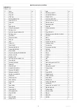
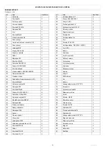
3. Before assembly check if there are all the parts in the box.
It is recommended that product should be assembled by at least two people
to avoid injuries.
ASSEMBLY INSTRUCTIONS (
Drawings
– p.
45-48)
STEP 1
Fix the front stabilizer (35) and rear stabilizer (36) to the main frame
(40) with a mounting screw (33), circular nut (23) and curved washer (22).
STEP 2
Plug the sensor (16) and (38) as well as the resistance control wire
(53) and (39), as shown in fig. 2. Fix the handlebar stem (15) to the main
frame (40) with the bolt (26), nut (27) and curved washer (22).
Note: tighten the screw (27) and curved washer (22) after step 3.
STEP 3
Fix the lower part of the grip arm (25L/R) to the handlebar stem
(15) with the bolt (18), washer (9) and D washer (19).
STEP 4
Fix the pedal guide (42L/R) to the crank with the pedal hinge
(46L/R), curved washer (50) and nylon nut (51L/R).
STEP 5
Fix the pedal (44) onto the pedal guide (42L/R) with the Phillips
head screw (43) and nylon nut (32).
STEP 6
Plug the sensors, as shown in fig.4. Fix the handlebar middle grip
(4) onto the handlebar stem (15) with the screw (8) and curved washer (9).
Fix the upper part of the grip arms (11L/R) to the lower parts (25L/R) with
the screw (21), curved washer (58) and circular nut (23).
STEP 7
Connect the wires (pulse sensor and the power cord of the
counter), as shown in fig. 5. Next fix the counter (1) onto the handlebar
stem (15) with the screw (2).
ATTENTION: before training make sure that all screws and nuts have been
well tightened.
NOTE: the end cap of the front stabilizer is movable, which makes it easy
to move the trainer to another place. The end caps of the rear stabilizer
serve to level the trainer..
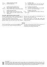
Levelling, moving the device
Before you start exercising, it is recommended to verify whether the bike is
positioned correctly.Level the equipment with the knobs of the front
stabilizer. To transport the device, raise it carefully on its front wheels
(Figure
– p. 49) and move to another place, holding it on both sides.
Resistance adjustment
The Resistance adjustment function allows to change resistance on the
pedals. High resistance requires larger effort while pedalling, whereas the
low one decreases the effort. Force of resistance is regulated by a knob
placed on the handlebar post. In order to decrease resistance, adjustment
knob should be turned towards the “1“ number whereas so as to increase
resistance, the knob should be turned towards the “8” number.
In order to achieve a satisfying effect, resistance level should be set during
a training..
MAINTENANCE
Prior to each use of the bicycle, make sure that all the bolts, nuts and
knobs are tightly fitting.
Aggressive cleaning products must not be used to clean the device. Use
a soft, damp cloth to remove dirt and dust. Clean sweat traces since
acidic pH may damage the upholstery.
The device should be kept in a dry place in order to protect it against
dampness and corrosion.
Should the computer work incorrectly, make sure that all the cables are
connected appropriately, especially the upper cable with the computer. If
the computer still does not work, make sure that batteries have been put
in appropriately and that they are not worn-out. If the readout on the
display screen is not legible or some elements are invisible, replace
batteries immediately.
In case of no resistance adjustment, make sure that the upper sensor
cable is well connected with the lower cable.
CAUTION: Due to the protection of the natural environment, worn-out
batteries, power adapters, motors etc. should not be disposed with
household wastes. Worn-out batteries, power adapters, motors etc. should
be taken to a point that will utilise them in agreement with the enforceable
law on environmental protection. It is recommended to check the power
cord and the plug periodically. Never pull the cord. In case of damage, the
device should not be used. Never repair the device on your own. Repairs
should be made by a qualified SPOKEY’s company employee.
POWER SUPPLY
Batteries: 1.5V AAA (2 pieces), not supplied with the bicycle
Inserting batteries
1. Insert two batteries at the back of the counter.
2. Make sure that the batteries are correctly positioned.
3. If the display is unreadable or only some segments are visible, remove
the batteries and re-insert them.
4. After removing the batteries, all function values
will be reset.
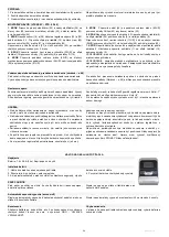
COUNTER
First start-up
Before the first start-up, make sure that all the cables have been connected
correctly and that the batteries have been inserted correctly.
The display will turn on once you press the button or when you start
pedaling.
Auto on-off
After 4 minutes, the meter enters the energy saving mode. All settings and
data are kept until restarting the meter.
In case the screen does not start, disconnect power supply and wait for 15
seconds.
Device error
If an incorrect reading appears on the counter, remove the batteries and reinsert them.
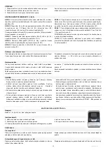
Buttons
MODE
selecting the counter functions
SET
setting time, distance, calories, and pulse, when the counter is not in
the SCAN mode.
RESET
resetting time, distance, calories, and pulse. To reset the values,
press the button for 3 seconds.
HOW TO OPERATE THE BIKE METER
Содержание 920877
Страница 2: ...1...
Страница 13: ...12 ARC 5 3 28 6 102 x 48 5 x 156 5 130 2 a 130 H C RU...
Страница 17: ...16 5 5 3 WEE...
Страница 43: ...42 1 SCHEMAT DIAGRAM SCH MA SCHEMA SH MA...
Страница 44: ...43...
Страница 46: ...45 1 KROK STEP INGSNIS SOLIS SCHRITT 2 KROK STEP INGSNIS SOLIS SCHRITT...
Страница 47: ...46 3 KROK STEP INGSNIS SOLIS SCHRITT 4 KROK STEP INGSNIS SOLIS SCHRITT...
Страница 48: ...47 5 KROK STEP INGSNIS SOLIS SCHRITT 6 KROK STEP INGSNIS SOLIS SCHRITT...
Страница 49: ...48 7 KROK STEP INGSNIS SOLIS SCHRITT...
Страница 51: ...50...
Страница 52: ...51...