IM-P145-02
ST Issue 2
8
3. Installation
Note: Before actioning any installation observe the 'Safety information' in Section 1.
Refering to the Installation and Maintenance Instructions, name-plate and Technical
Information Sheet, check that the product is suitable for the intended installation.
3.1
Check materials, pressure and temperature and their maximum values. If the maximum
operating limit of the product is lower than that of the system in which it is being fitted,
ensure that a safety device is included in the system to prevent overpressurisation.
3.2
Determine the correct installation situation and the direction of fluid flow.
3.3
Remove plastic protective covers from connections.
3.4
If the trap is to discharge to atmosphere ensure that it's to a safe place, the discharging
fluid may be at a temperature of 100
°
C (212
°
F).
3.5
The trap must be fitted with the float arm in a horizontal plane so that it rises and falls
vertically. This applies to all installation flow directions.
3.6
Although the standard flow configuration is right to left (R-L) the connection orientation
can be changed on site by undoing the four cover bolts and moving the cover to the
preferred flow orientation.
Note:
A new gasket must always be fitted.
Warning: The cover gasket contains a thin stainless steel support ring which may
cause physical injury if not handled and disposed of carefully.
3.7
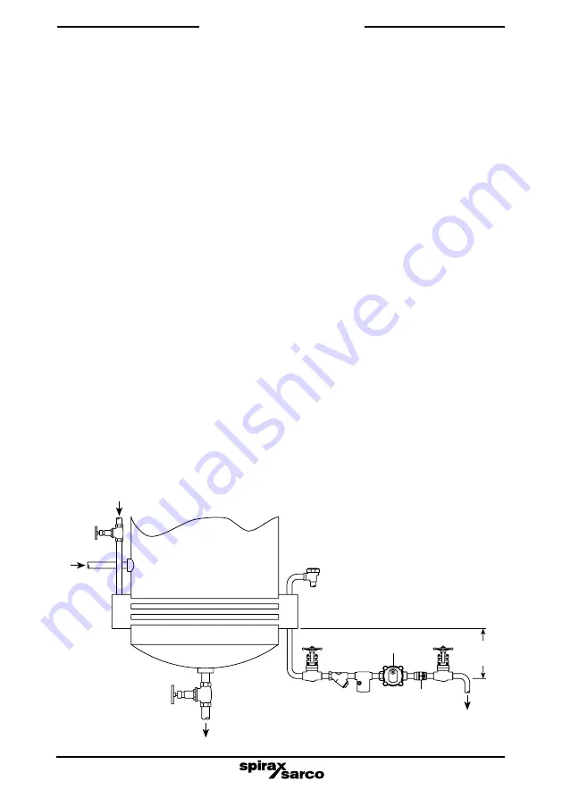
Traps should be fitted below the outlet of the steam system with a small drop leg
immediately preceding the trap - Typically 150 mm (6") see Figure 4. If no drop leg is
allowed then it may be possible (under low load conditions) for steam to flow over the
condensate in the bottom of the pipe and reach the trap.
3.8
Always fit a non-return (check) valve downstream of any steam traps which discharge
into condensate return lines where back pressure is experienced. This is most
commonly caused by a rising condensate line. The check valve will prevent the steam
space flooding when the inlet pressure is reduced or the steam is shut off. Use a suitable
valve such as the Spirax Sarco DCV41, see Figure 4.
Fig. 4 Evaporator
Heater
Steam in
Product
in
Air vent
Product out
FTS14
150 mm (6")
mimimum
DCV41
Condensate
out
Содержание FTS14
Страница 2: ...IM P145 02 ST Issue 2 2 ...
Страница 12: ...IM P145 02 ST Issue 2 12 ...


