SpinCore PulseBlasterDDSII
LabVIEW Extensions
Error Terminals
All of the SubVIs have error input and output terminals. When a VI is built, the “error
out” terminal of a subVI should be connected to the “error in” terminal of the following
subVI. These terminals are used to help facilitate sequential execution of the functions, as
well as provide debugging information to the user if an error occurs in the VI. See Figure 6
and Figure 7 for an example of these terminals. When chaining, the order of the subVIs
corresponds to the order in which the functions will be called.
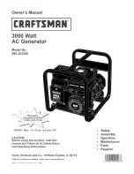
LabVIEW Program Flow
The LabVIEW Block diagram is set up to independently control the four major
functions (start/restart, stop/reset, load, change) using four while loops running in parallel.
Within each loop is another loop that continuously waits for the specified button to be
pressed. Once the button is pressed, the inner loop will exit and program flow will be
passed to the chain of subVIs. After the chain of functions complete, program flow will
return to the inner loop to wait for the button again. An example of this is shown in Figure
8.
14
2011-04-29
Figure 8: LabVIEW Program Flow Example
www.spincore.com