5
IV. OPERATING INSTRUCTIONS
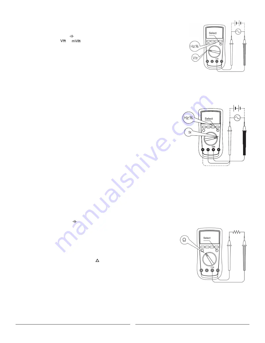
A. AC/DC VOLTAGE MEASUREMENT (See Figure 2)
To measure voltage, connect the Meter as follows:
1. Insert the red test lead into the input terminal and the black test lead into the
COM terminal.
2. Set the rotary switch to or : DC measurement is default or press the
SELECT button to
switch show the AC and DC symbols.
3. Connect the test leads across with the object being measured.
The measured value shows on the display and will also show the TRMS value.
Display TRMS Value: If the frequency and duty cycle values are needed at this moment, press the Hz
button to obtain relative data. The input amplitude concerning these two aspects should follow the
requirements as stated below:
- Input Amplitude: (DC electric level is zero)
- Input Amplitude:
≥
rangeX30%
- Frequency respouse:
≤
1kHz
NOTE: In each range, the Meter has an input impedance of 10
Ω
except the mV range where the input
impedance is 3000M
Ω
. This loading effect can cause measurement errors in high impedance
circuits. If the circuit impedance is less than or equal to 10K
Ω
, the error is negligible (0.1 % or less).
B. AC/DC CURRENT MEASUREMENT (See Figure 3)
To measure current, connect the Meter as follows:
1. Insert the red test lead into the mA / μA or 10AMax input terminal and the black test lead
into the
COM terminal.
2. Set the rotary switch to μA, mA, or A.
3. The Meter defaults to the DC current measurement mode. show the AC and DC symbols current
measurement function, press the
SELECT button.
4. Connect the test lead in series to the return circuit to be tested.
The measured value shows on the display and will also show the TRMS value.
5. Press Hz% to obtain the frequency and duty cycle value.
Display TRMS Value: If the frequency and duty cycle values are needed, press the Hz/% button
to obtain relative data. The input amplitude concerning these two aspects should follow the
requirements as stated below:
- Input Amplitude: (DC electric level is zero)
- lnputAmplitude:
≤
rangeX30%
- Frequency response:
≤
1kHz
NOTE:
• If the value of current to be measured is unknown, use the maximum measurement position, and reduce the range step by step until a
satisfactory reading is obtained.
• Each measurement time for >5A current should be less than 10 seconds and the interval time
between 2 measurements should be greater than 15 minutes.
• When current measurement has been completed, disconnect the connection between the testing leads
and the circuit under test, and remove the testing leads from the input terminals of the Meter.
C. MEASURING RESISTANCE (See Figure 4)
To measure resistance, connect the Meter as follows:
1. Insert the red test lead into the input terminal and the black test lead into
the
COM terminal.
2. Set the rotary switch to
Ω
resistance measurement (
Ω
) is default or press the
SELECT button
to select
Ω
measurement mode.
3. Connect the test leads across with the object being measured. If there is lead on the resistor
or SMT resistor. The measured value shows on the display.
NOTE:
• The test leads can add 0.2
Ω
to 0.5
Ω
of error to resistance measurements. To obtain precision
readings in low-resistance measurement, short-circuit the input terminals beforehand and use
the relative measurement function button
REL .This will automatically subtract the value
measured when the testing leads are short circuited from the reading.
• If
Ω
reading with shorted test leads is not
≤
0.5
Ω
, check for loose test leads or other reasons.
• For high-resistance measurements (>1M
Ω
), it is normal to take several seconds to obtain a
stable reading. To obtain stable reading, use shorter test leads to carry out readings.
• The LCD displays
OL indicating open-circuit for the tested resistor or the resistor value is
higher than the maximum range of the Meter.
• When the resistance measurement has been completed, disconnect the connection between
the testing leads and the circuit under test, and remove the testing leads from the input terminals of the Meter.
Figure 2
Figure 3
Figure 4
V
Ω
Hz
V
Ω
Hz


