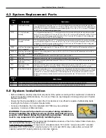
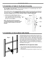
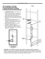
Sperian MILLER Vi-Go Скачать руководство пользователя страница 9

9

U s e r   I n s t r u c t i o n s   -   E n g l i s h

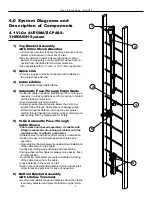
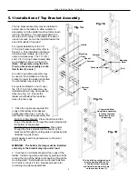
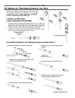
5.1 Installation of Top Bracket Assembly

Mounting

Plate

Washer

Fastener

Cap

Fastener

U-Bolt

Fig. 1a

Fig. 1d

Fastener

Washers

Mounting

Plate

Bolt

Fig. 1b

Shown with Extra 

Rung Clamp Assembly 

to reduce the loads 
transmitted to each 

ladder rung.

Fig. 1c

This installation configuration ► 

is only permitted with the 5 ft. 

(1.5m) top bracket assembly

and limits the number of users

on the system to one (1).

The top bracket assembly may be installed to 
extend above the ladder to allow workers to 
step safety onto the platform without disconnect-
ing from the lifeline.  It is recommended to be 
mounted at the center of the ladder for ease of 
use and access, but can be installed toward the 
side of the ladder if required.

For typical installation of the 5 ft. 
(1.5m) top bracket assembly, refer to 

Figure 1a.  This installation configura

-

tion will accommodate up to four (4) 
users simultaneously.  The 7 ft. (2m) 
and 10 ft. (3m) top bracket assemblies 
are installed as shown in Figure 1b.  
[

Note:  All systems using the 10 ft.

(3m) top bracket assembly are lim-
ited to two (2) users.]

An extra rung clamp assembly may 
be used in the installation of the top 
bracket to lower the loads transmitted 
to each ladder rung (see Fig. 1c).  

For systems limited to one (1) user, 
the 5 ft. (1.5m) top bracket may be 
installed with two rung clamp assem-
blies (see Fig. 1d).  Ensure the 
ladder will withstand the loads be-
tween the two rungs.


1.  Place the top bracket against the 
rungs of the ladder at the desired 
height (see either Fig. 1a or 1b).  In-

stall bottom rung clamp assembly first.  

For 5 ft. (1.5m) bracket:  Place U-bolt around the 
rung of the ladder and through the holes provided at 
the bottom of the bracket.  
For 7 ft. (2m) or 10 ft. (3m) bracket:  Place bolts 
through the holes provided at the bottom of the 
bracket and through mounting plate on opposite side 
of ladder rung as shown.

Install washers and torque fasteners to 20 plus or 
minus 2 ft. lbs.

WARNING:  The bottom U-clamp must be installed 
correctly or the bracket may slip under load.

2.  Continue to hold bracket against the rungs of the 
ladder.  Install rung clamp assembly by placing U-bolts 
around the rung of the ladder and inserting through the 
mounting plate.  Install washers and torque fasteners 
to 20 plus or minus 2 ft. lbs.  Repeat procedure for 
remaining rung clamp assemblies.

Содержание MILLER Vi-Go

Страница 1: ......

Страница 2: ...tem Replacement Parts 5 0 System Installation 8 14 5 1 Installation of Top Bracket Assembly 5 2 Installation of Cable to Top Bracket Assembly 5 3 Installation of Intermediate Cable Guides 5 4 Installa...

Страница 3: ...his equipment All authorized persons users must reference the regulations governing occupational safety as well as applicable standards i e ANSI or CSA Refer to product labeling for information on spe...

Страница 4: ...rson falling will not strike a user below Note According to ANSI A14 3 only one worker may be on the system between cable guides Fall Clearance Ensure that adequate clearance exists in the fall path t...

Страница 5: ...forces generated by arresting a fall The load requirements vary due to number of users on the system and installation to the structure i e number of rung clamp assemblies used For calculation purposes...

Страница 6: ...ts upside down installation of the cable sleeve to the cable Hands free trailing while climbing and descending Spring activated mechanisms always move device back to initial position Dual locking mech...

Страница 7: ...formation 4 Manual Pass Through Cable Guide Holds the cable in position securing it away from the ladder or structure Fully convertible to accommodate low and high wind conditions Manual pass through...

Страница 8: ...0 flat washers and two M10 1 5mm locknuts TRCG Manual Pass Through Cable Guide Galvanized steel cable bracket with convertible polyurethane cable retainer head includes 3 8 16 x 1 1 4 x 2 U Bolt two 3...

Страница 9: ...im ited to two 2 users An extra rung clamp assembly may be used in the installation of the top bracket to lower the loads transmitted to each ladder rung see Fig 1c For systems limited to one 1 user t...

Страница 10: ...and bent over so that it will not back out DO NOT USE SYSTEM IF COTTER PIN IS MISSING 5 3 Installation of Intermediate Cable Guides Intermediate Cable Guides are designed to keep the climber from exc...

Страница 11: ...guide on top of ladder rung see Fig 4a 2 Install U bolt around underside of ladder rung and through holes provided in cable guide 3 Install washers and torque fasteners to 20 plus or minus 2 ft lbs 5...

Страница 12: ...ensioning of cable is achieved install jam nut against tensioning nut 6 Discard excess cable by cutting below the lower saddle clip leaving approximately 3 of cable below the lower saddle clip 3 is re...

Страница 13: ...date variable cable lengths These options are compatible with 3 8 diameter approved cable only 1 Feed cable around cable thimble turning back 5 1 4 of cable from thimble end Install first cable clip o...

Страница 14: ...able lifeline according to the manufacturer s instructions 3 Attach the cable sleeve to the front attachment point designated for ladder climbing of the full body harness using a Miller approved auto...

Страница 15: ...ually inspect before each use Regular inspection by a competent person for wear damage or corrosion should be a part of your safety program Replace equipment if any of the defective conditions explain...

Страница 16: ...prouv par Aprobado por Approved by Approuv par Aprobado por Approved by Approuv par Aprobado por Approved by Approuv par Aprobado por Approved by Approuv par Aprobado por Approved by Approuv par Aprob...

Страница 17: ...rotection contre les chutes Miller sont soumis des essais pour v rifier qu ils r sistent une usure normale ils ne sont cependant pas indestructibles et peuvent s endommager en cas de mauvaise utilisat...

Страница 18: ...treet Franklin PA 16323 USA Toll Free 800 873 5242 Fax 800 892 4078 Download this manual at www millerfallprotection com T l chargez ce manuel l adresse www millerfallprotection com Puede bajar por In...

Отзывы: