U s e r I n s t r u c t i o n s - E n g l i s h
10
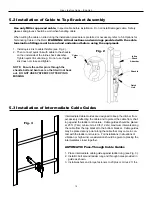
5.2 Installation of Cable to Top Bracket Assembly
Use only Miller approved cable.
Inspect cable before installation. Do not install damaged cable. Safety
glasses and gloves should be worn when handling cable.
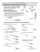
When cutting the cable on site during the installation procedure is preferred or necessary, refer to 5.6 Options for
Terminating Cable in the Field.
WARNING: All instructions and warnings provided with the cable
termination fittings must be read and understood before using the equipment.
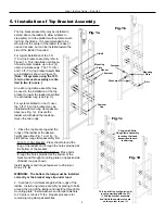
1. Install quick link to cable thimble (see Fig. 2).
2. Then connect quick link with cable to the shackle
on the underside of the inline shock absorber.
Tighten quick link until snug. Do not use if quick
link does not close and tighten.
NOTE: Ensure the cotter pin is through the
shackle bolt and bent over so that it will not back
out. DO NOT USE SYSTEM IF COTTER PIN IS
MISSING.
5.3 Installation of Intermediate Cable Guides
Intermediate Cable Guides are designed to keep the climber from
excessively deflecting the cable and to protect the cable from chaf
-
ing against the ladder or structure. Cable guides should be placed
at 25 ft. (7.6m) minimum to 40 ft. (12.2m) maximum intervals
along
the cable from the top bracket to the bottom bracket. Cable guides
may be placed at any point along the cable that may come in con-
tact with the ladder or structure. For installations in situations of
vibration or high wind, consideration should be given to placing the
intermediates closer together.
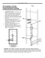
AUTOMATIC Pass-Through Cable Guides
1. Place intermediate cable guide against ladder rung (see Fig. 3).
2. Install U-bolt around ladder rung and through holes provided in
guide as shown.
3. Install washers and torque fasteners to 20 plus or minus 2 ft. lbs.
Fig. 3
Inline
Shock
Absorber
Shackle
Quick
Link
Cotter
Pin
Fig. 2
Содержание MILLER Vi-Go
Страница 1: ......


