Page
15
of
98
118157-001 Rev C
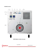
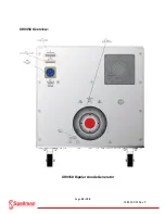
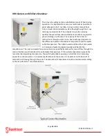
XRV225kV Overview:
XRV225kV (Rear Panel)
The 225kV XRV Generator measures a compact 17” W x
18.90” (including castors) x H 30.72” D (excluding cable
well). The assembly includes lockable castors for easy
moving. The rear of the chassis has all of the necessary
connectors for power input, controls, monitoring, and kV
output. Each connector on the rear panel clearly marked
for installation purposes. The main and auxiliary input
includes an Amphenol style mating connector with an
additional DB-25 pin connector for the I/O analog
connection. The high voltage output mates with a
standard R-28 type connector. These are available from
Spellman High Voltage Corp. in different lengths and
configurations for installation of the X-ray tube. Standard Graphical User Interface (GUI) software is
included with the XRV 225 Generator. A personal PC is required for installation. The user has the option
of connection to a USB, Ethernet or Com Port. The control and monitoring of the XRV225 also includes
an analog I/O connector for custom configurations. An additional optional touch screen controller
(XRVC) is also available from Spellman High Voltage Corp..
Содержание XRV Sub-system
Страница 1: ...SPELLMAN HIGH VOLTAGE XRV SUBSYSTEM INSTALLATION MANUAL ...
Страница 13: ...Page 13 of 98 118157 001 Rev C XRV 160kV Overview 400Vac 3Ø Input ...
Страница 17: ...Page 17 of 98 118157 001 Rev C XRV225kV Overview XRV225 400Vac 3Ø 6kW Unit ...
Страница 21: ...Page 21 of 98 118157 001 Rev C XRV450 Overview XRV450 Bipolar Cathode Generator ...
Страница 22: ...Page 22 of 98 118157 001 Rev C XRV450 Overview XRV450 Bipolar Anode Generator ...
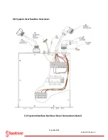
Страница 25: ...Page 25 of 98 118157 001 Rev C I O System Interface Box Overview I O System Interface Box Front Panel Detail ...
Страница 28: ...Page 28 of 98 118157 001 Rev C XRVC Controller Overview XRVC Controller Rear Panel Detail ...
Страница 34: ...Page 34 of 98 118157 001 Rev C XRV Unipolar System Diagram Typical Unipolar System Minimal Requirements ...
Страница 36: ...Page 36 of 98 118157 001 Rev C XRV Bipolar System Diagram Typical Bipolar System Minimal Requirements ...
Страница 51: ...Page 51 of 98 118157 001 Rev C System Grounding Detail and HV Cable Connections ...
Страница 58: ...Page 58 of 98 118157 001 Rev C Interlock Communication Connections Unipolar Basic RS 232 Cable ...
Страница 59: ...Page 59 of 98 118157 001 Rev C Interlock Communication Connections Unipolar Basic Ethernet Cable USB Cable ...
Страница 66: ...Page 66 of 98 118157 001 Rev C ...
Страница 67: ...Page 67 of 98 118157 001 Rev C Power Source Connections Unipolar Basic ...
Страница 68: ...Page 68 of 98 118157 001 Rev C Power Source Connections Unipolar Basic ...
Страница 72: ...Page 72 of 98 118157 001 Rev C Power Connections I O System Interface Box ...
Страница 76: ...Page 76 of 98 118157 001 Rev C Main Input Power Connections I O System Interface Box ...
Страница 77: ...Page 77 of 98 118157 001 Rev C I O Subsystem Interface Box System Diagram ...
Страница 82: ...Page 82 of 98 118157 001 Rev C Flash Drive USB installation Step 1 Flash Drive USB installation Step 2 ...
Страница 83: ...Page 83 of 98 118157 001 Rev C Flash Drive USB installation Step 3 Flash Drive USB installation Step 4 ...
Страница 89: ...Page 89 of 98 118157 001 Rev C X Ray Tube Filament Calibration Setup ...


