


EVA
Manual
16
118144
‐
001
REV.
A
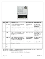
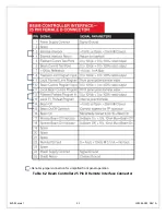
Pin
Signal
Parameters
1
Power Supply Common
Power Supply Ground
2
Reset/HV Inhibit
Toggle to reset latched faults, Ground = Inhibit, Open = HIGH VOLTAGE ON
3
External Interlock
+24Vdc @ open, <25mA @ closed
4
External Interlock Return
Return for External Interlock. Pins 3 and 4 must be connected to HV enable
5
mA Test Point
0-10Vdc = 0-100% rated output, Zout = 1k
Ω
, 1%
6
kV Test Point
0-10Vdc = 0-100% rated output, Zout = 1k
Ω
, 1%
7
+10Vdc Reference
+10Vdc @ 1mA
8
mA Program Input
0-10Vdc = 0-100% rated output, Zin =>10M
Ω
, jump to pin 8 for local control
9
Local mA Program Output
0-10Vdc = 0-100% rated output, front panel potentiometer
10
kV Program Input
0-10Vdc = 0-100% rated output, Zin =>10M
Ω
, jump to pin 11 for local control
11
Local kV Program Output
0-10Vdc = 0-100% rated output, front panel potentiometer
12
Remote Power On Output
24Vdc @ open, <25mA @ closed
13
Remote Power On Return
Return for Remote Power On
14
Remote HV OFF
+24Vdc @ open, <25mA @ closed, connect to pin 15 for front panel operation
15
Remote HV OFF/ON Common
Remote HV OFF/ON Common
16
Remote HIGH VOLTAGE ON
+24Vdc @ open, <25mA @ closed, momentarily connect to pin 15 for HV enable
17
HIGH VOLTAGE OFF Indicator
+24Vdc @ 25mA = HV OFF
18
HIGH VOLTAGE ON Indicator
+24Vdc @ 25mA = HIGH VOLTAGE ON
19
Power Supply Common
Power Supply Ground
20
+24Vdc Output
+24Vdc @ 100mA, maximum
21
Voltage Mode Status
Open collector, Low = Active, 35V maximum @ 10mA
22
Current Mode Status
Open collector, Low = Active, 35V maximum @ 10mA
23 n/c
24
Interlock Closed Status
Open collector, Low = Active, 35V maximum @ 10mA
25 n/c
26 Spare
27 Spare
28
Remote Overvoltage Adjust
0-10Vdc = 0-105% rated output
29 n/c
30
Over Voltage Fault
Open collector, Low = Active, 35V maximum @ 10mA
31
Over Current Fault
Open collector, Low = Active, 35V maximum @ 10mA
32
System Fault
Open collector, Low = Active, 35V maximum @ 10mA
33
RGLT Error Fault
Open collector, Low = Active, 35V maximum @ 10mA
34
ARC
Open collector, Low = Active, 35V maximum @ 10mA
35
Over Temp Fault
Open collector, Low = Active, 35V maximum @ 10mA
36
AC Fault
Open collector, Low = Active, 35V maximum @ 10mA
37 Spare
38 Spare
39 Spare
40 Spare
41 Spare
42
Short to pin 43
Connect pin 42 and pin 43 together in all configurations
43
Short to pin 42
Connect pin 42 and pin 43 together in all configurations
44
+5Vdc Output
+5Vdc @ 100mA, maximum
45
+15Vdc Output
+15Vdc @ 100mA, maximum
46
-15Vdc Output
-15Vdc @ 10mA, maximum
47
RS-232 Tx
RS-232 Tx
48
RS-232 Rx
RS-232 Rx
49
RS-232 GND
RS-232 GND
50
Power Supply Common
Power Supply Ground
=
Denotes
jumper
connection
for
simplified
local
front
panel
control
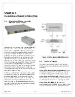
Figure
3.10
JB1
Rear
Panel
Interface
Connecter


