


EVA
Manual
24
118144
‐
001
REV.
A
EVA
BEAM
CONTROLLER
OPERATING
INSTRUCTIONS
6.10
Operation
WARNING
THIS
EQUIPMENT’S
OUTPUT
IS
REFRENCED
TO
DANGEROUS
VOLTAGES
THAT
MAY
BE
FATAL.
PROPER
GROUNDING
OF
ALL
HIGH
VOLTAGE
EQUIPMENT
IS
ESSENTIAL.
WARNING
BEFORE
CONNECTING
THE
POWER
SUPPLY
TO
THE
AC
LINE,
FOLLOW
THIS
STEP
‐
BY
‐
STEP
PROCEDURE.
DO
NOT
CONNECT
THE
POWER
SUPPLY
TO
THE
AC
LINE
UNTIL
STEP
‘G’
IS
REACHED.
FAILURE
TO
FOLLOW
THESE
PROCEDURES
MAY
VOID
THE
WARRANTY.
A)
Insure
that
the
input
power
cable
is
disconnected
from
the
rear
panel
IEC320
connector.
B)
Check
the
input
voltage
rating
on
the
rear
panel
identification
tag
and
make
certain
that
this
is
the
rating
of
the
available
power
source.
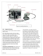
C)
PROPER
GROUNDING
TECHNIQUE
:
The
chassis
of
the
high
beam
controller
and
the
gun
output
box
must
be
properly
grounded.
Connect
the
ground
cable
from
the
gun
output
box
to
the
beam
controller
using
the
¼
‐
20
ground
studs.
Connect
the
ground
cable
from
the
beam
controller
to
the
EVA
high
voltage
power
supply
using
the
¼
‐
20
ground
studs.
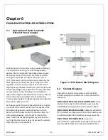
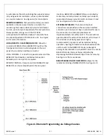
See
Figure
6.2
for
a
typical
operating
setup.
A
six
foot
long,
detachable
IEC320,
three
‐
wire,
unterminated
line
cord
is
provided
for
connecting
to
the
AC
input
supply.
The
BROWN
wire
is
LINE
and
the
BLUE
wire
is
NEUTRAL.
The
GREEN
wire
is
for
chassis
safety
ground
connection.
This
is
a
safety
ground
connection
and
is
NOT
adequate
for
system
grounding
purposes.
MAKE
CERTAIN
THE
EVA
HIGH
VOLTAGE
POWER
SUPPLY
IS
DISCONNECTED
FROM
THE
AC
POWER
SOURCE
AND
TURNED
OFF
FOR
A
MINIMUM
OF
5
MINUTES
BEFORE
PROCEEDING!
D)
Plug
the
captive
(yet
field
replaceable)
high
voltage
output
cable
attached
to
the
gun
output
box
into
the
rear
panel
high
voltage
connector
of
the
EVA
high
voltage
power
supply
and
secure
properly.
E)
Connect
the
captive
two
conductor
filament
output
cable
that
exits
the
gun
output
box
to
the
filament
of
the
electron
gun.
Either
wire
can
be
connected
to
which
ever
terminal
of
the
filament
desired
as
there
is
no
polarity
orientation.
Make
certain
the
connections
are
secure
due
to
the
high
current
output
(35
amp
standard
or
optional
50
amp)
of
the
filament
power
supply.
F)
For
initial
turn
‐
on,
rotate
the
front
panel
Emission
(beam)
Current
control
potentiometer
fully
counter
‐
clockwise
to
the
zero
position.
Rotate
the
front
panel
Filament
Limit
Set
control
potentiometer
fully
counter
‐
clockwise
to
the
zero
position.
G)
The
input
power
cable
may
now
be
connected
to
the
AC
power
line.
H)
Reconnect
the
AC
power
source
to
the
EVA
high
voltage
power
supply
and
the
EVA
beam
controller.
I)
Depress
the
CONTROL
POWER
ON
switch
on
the
EVA
high
voltage
power
supply
front
panel.
J)
Observe
that
the
front
panel
meters
are
illuminated
and
the
green
BEAM
OFF
indicator
is
illuminated
on
the
EVA
beam
controller
chassis.
Additionally
observe
that
the
front
panel
meters
are
illuminated
and
the
green
HIGH
VOLTAGE
OFF
indicator
is
illuminated
on
the
EVA
high
voltage
power
supply
chassis.
K)
Rotate
the
Filament
Limit
potentiometer
slowly
clockwise
until
the
beam
controller
filament
current
meter
displays
the
factory
preset
10
amp
preheat
level.
The
filament
is
now
operating
at
a
10
amp
filament
current
level.
L)
Depress
and
hold
in
the
BEAM
OFF
switch.
The
front
panel
meters
will
now
display
the
preset
value
of
the
Emission
(beam)
Current
control
potentiometer
and
the
Filament
Limit
Set
control
potentiometer.
To
preset


