background image

Transmitter Stick Operation

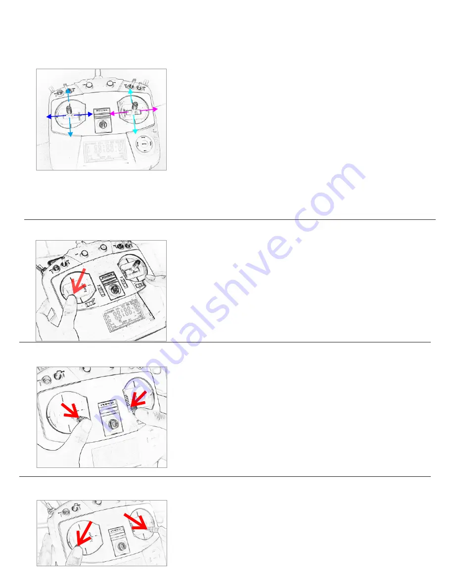
Unlock and start motors

Lock and stop motors

Diagrams of Flying Operations

Throttle  stick  (AB):

  The  throttle  stick  controls  the  up  and 

down of the aircraft. When the throttle stick is at the mid point, 
the  aircraft  hovers  in  the  air.  pushing  the  throttle  to  A,  the 
aircraft  ascends  and  pulling  the  throttle  to  B,  the  aircraft 
descends.

Yaw  stick  (CD): 

The


yaw  stick  is  used  to  adjust  yaw 

directions.  Pull  it  to  the  left  and  the  aircraft  will  rotate  in  the 
counterclockwise  direction.  Push  it  to  the  right  and  the 
aircraft will rotate in the clockwise direction.

Pitch  stick(EF):

  The  pitch  stick  controls  the  forward  and 

backward  directions  of  the  aircraft.

Pull  it  to

E

  and  the  aircraft 

will fly forward ;Pull it to F and the aircraft will fly  backward  .

Roll  stick  (GH):

  The  roll  stick  controls  the  left  and  right 

directions  of  the  aircraft.

Pull  it  toG  and  the  aircraft  will  fly  to 

the  left  direction  ;Pull  it  to  H  and  the  aircraft  will  fly  to  right 
direction

Make  sure  the  aircraft  is  placed  on  a  horizontal 
place

Pull  the  left  stick  to  the  left  bottom  and  wait 

about 2 seconds until the back light flashes. Release 
the  stick  to  the  mid  point  and  finish  the  basic  self-
calibration.

Basic self-calibration

A

B

C

D

E

F

G

H

Pull the left stick to the right bottom and pull the right 
stick to the left bottom at the same time to unlock and 
start the motors

Pull  the  left  stick  to  the  left  bottom  and  pull  the  right 
stick to the right bottom to lock and stop motors.

3

Содержание SP-Basic20

Страница 1: ...For SP Basic20 Unmanned rotorcraft User Manual...

Страница 2: ...sible Malfunctions and Solutions Diagrams of Flying Operations 5 5 1 5 6 6 3 3 3 3 3 4 4 4 Transmitter Stick Operation Unlock and start motors Lock and stop motors Basic self calibration Propeller Ins...

Страница 3: ...onditions due to water sand or other unknown materials entering the aircraft or due to obviously defective components or parts or when the low voltage protection alarm has been triggered 7 Damages or...

Страница 4: ...8mm 9 inch Propeller Package size Size X360X100MM Large battery compartment Can be Placed two 3S flight time 15 30minutes 2 NOTE Speedwolf SP Basic20 can install stainless steel wire Landing Gear and...

Страница 5: ...and backward directions of the aircraft Pull it toE and the aircraft will y forward Pull it to F and the aircraft will y backward Roll stick GH The roll stick controls the left and right directions o...

Страница 6: ...LEDs LED1 2 3 4 ash slowly about once every 1 5 seconds this indicates battery voltage is low and you should get ready to land the aircraft do not y away 2 Level II Low Voltage Protection when the LED...

Страница 7: ...time and keep alert to Low Voltage signals Low Voltage Alert is to indicate that the battery cannot provide enough power for the aircraft and to warn you to land the aircraft it is triggered ASAP to a...

Страница 8: ...them Try again until the propellers could rotate well In case the propellers still can not rotate have a try to push a propeller by hand to aid its rotation If they keep still again please return the...

Страница 9: ...http www speedwolf net rotorcraft...

Отзывы: