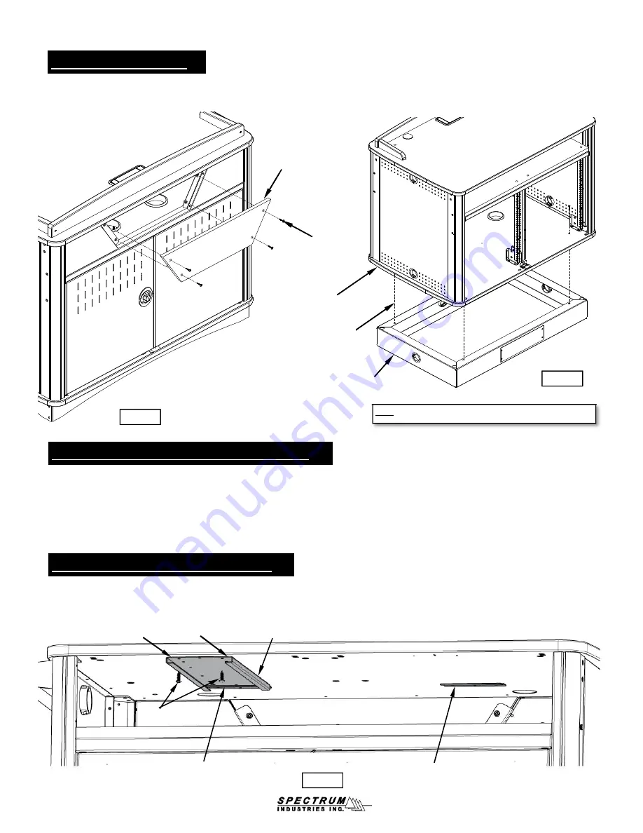
A. To access the upper keyboard / rack rail area from the back, remove the (4) JC bolts and remove the back panel.
Figure 3
.
B. Replace the panel and tighten the JC bolts securely.
Back Panel Removal
JC bolt
Back Panel
Figure 3
Figure 4
Toe Kick
Lectern
Note
: (4) fasteners are req'd to anchor toe-kick to floor.
1/4-20 x 35mm JC bolts
(4) req'd
0103148XR6 Page 3 of 9
A. To access the upper keyboard / rack rail area from the back, remove the (4) JC bolts and remove the back panel.
Figure 3
.
B. Replace the panel and tighten the JC bolts securely.
Back Panel Removal
JC bolt
Back Panel
Figure 3
Figure 4
Toe Kick
Lectern
Note
: (4) fasteners are req'd to anchor toe-kick to floor.
1/4-20 x 35mm JC bolts
(4) req'd
Floor Anchoring (Toe Kick models only)
A. If your Media Director is equipped with a toe-kick, and you wish to attach it to the floor, the toe-kick will need to be detached from the
lectern. To detach, remove the (4) 1/4-20 x 35mm JC bolts (one on each corner) from inside the lectern.
B. Carefully lift the lectern off the toe-kick. This will require several people.
Figure 4
.
C. Locate the toe-kick into the final position on the floor and mark the (4) mounting hole locations on the floor.
D. Drill holes into the floor and anchor the toe-kick with appropriate fasteners. (The toe-kick mounting holes are approximately 1/2" dia.)
E. Carefully lift the lectern back onto the toe-kick and align the (4) mounting holes.
F. Re-attach the lectern to the toe-kick with the previously removed JC bolts.
Attaching Optional Keyboard Tray
A. Hook the keyboard slide/track into one of the pre-installed clips under the left or right-side of the work surface.
Figure 5
.
B. Attach slide/track to the work surface using (2) screws (from the keyboard tray kit) and the pre-drilled work surface holes.
C. Slide the keyboard tray into the slide/track.
D. Refer to the keyboard tray instructions for remainder of installation.
Figure 5
screws
right slide/track clip
left slide/track clip
slide/track
0103148XR6 Page 3 of 9


