background image

I-2                Index  

User’s Manual Pub. 0300322-01 Rev. A 


Содержание Micro800 2085-IR8-SC

Страница 1: ...User s Manual Pub 0300322 01 Rev A ...

Страница 2: ...y product or service referenced herein No patent liability is assumed by Spectrum Controls Inc with respect to the use of any of the information products circuits programming or services referenced herein The information in this owner s guide is subject to change without notice Limited Warranty Spectrum Controls Inc warrants that its products are free from defects in material and workmanship under...

Страница 3: ... 2 4 2 4 3 Module Description 2 4 2 4 4 Insert Module Next to the Controller 2 5 SECTION 2 5 FIELD WIRING CONNECTIONS 2 7 Wiring Diagram 2 7 CHAPTER 3 CONFIGURING THE 2085 IT8 SC IT16 SC USING CCW 3 1 SECTION 3 1 INTRODUCTION 3 1 SECTION 3 2 2085 IT16 SC AOPS 3 2 SECTION 3 3 CCW CONFIGURATION TAB 3 6 SECTION 3 4 SETTING CONFIGURATION PARAMETERS USING MCC 3 9 SECTION 3 5 SOFTWARE INFORMATION 3 14 3...

Страница 4: ...Junction Compensation Weighted Profile 3 28 3 6 8 Input ADC Filter Frequencies Description 3 28 3 6 9 Open Circuit Detection Description 3 28 3 6 10 Process Alarm and Latching 3 30 SECTION 3 7 UNDER OVER RANGE ALARMS 3 31 SECTION 3 8 ADC ALARM 3 32 SECTION 3 9 DATA NOT READY ALARM 3 32 3 9 1 Module Specific Hardware Errors 3 33 3 9 2 Module Specific Configuration Errors 3 34 SECTION 3 10 TECHNICAL...

Страница 5: ...er Manual Be sure to review the warnings provided in this document before you start installing a module in a system How to Use This Manual As much as possible we organized this manual to explain in a task by task manner how to install configure program operate and troubleshoot a control system using the Micro800TM 8 16 Channel Thermocouple and Millivolt Analog Input Modules Related Documentation T...

Страница 6: ...n Wiring and Grounding Guidelines Allen Bradley publication 1770 4 1 for additional installation requirements NEMA Standards publication 250 and IEC publication 60529 as applicable for explanations of the degrees of protection provided by different types of enclosure 1770 4 1 NEMA 250 2014 IEC 60529 Declarations of conformity certificates and other certification details Product Certification websi...

Страница 7: ...gs and sub headings WARNING Identifies information about practices or circumstances that can lead to personal injury or death property damage or economic loss These messages help you to identify a hazard avoid a hazard and recognize the consequences ATTENTION Actions ou situations risquant d entraîner des blessures pouvant être mortelles des dégâts matériels ou des pertes financières Les messages ...

Страница 8: ...viii Micro800TM 8 16 Channel Thermocouple and Millivolt Analog Input Modules User s Manual Pub 0300322 01 Rev A ...

Страница 9: ...ts Expansion I O buses The minimum system requirement in which an Expansion I O Module can be installed is a Micro850 or Micro870 Controller and a controller power supply Section 1 1 General Description NOTE The module firmware released as revision 1 1 is compatible with the Micro850 Series A B PLCs and Micro870 Series A PLC with its PLC firmware revision 11 011 and under The number of 2085 IT16 S...

Страница 10: ...resistor is not used and the channel accepts the voltage source directly Direct thermocouple For both modules two cold junction sensors are available to be placed at the top and bottom of each terminal block The module measures thermocouple and CJ Sensors voltages and converts the results to a temperature reading Two physical Cold Junction Compensation sensors one at top one at the bottom of each ...

Страница 11: ...t in 16 bit resolution The modules measure thermocouple and CJ Sensors voltages and convert the results to a temperature reading Each input channel is individually configurable via Rockwell provided Connected Component Workbench CCW software for the Micro850 and Micro870 family controllers or with the Module Configuration Converter MCC utility from Spectrum Controls Inc The module is factory calib...

Страница 12: ...ial contact Radiated Immunity 10 V M with 200 Hz square wave 50 Pulse 100 AM at 900 and at 1890 MHz 10 V M with 1 kHz sine wave 80 AM from 80 2000 MHz 3 V M with 1 kHz sine wave 80 AM from 2000 6000 MHz Input modes Thermocouples and millivolt ranges Inputs per module 8 channels 8 thermocouple millivolt inputs and 2 CJC input channels Inputs per module 16 channels 16 thermocouples millivolt inputs ...

Страница 13: ...ues 0 5 ºC maximum for 20 ºC to 90 ºC input values CJC Total accuracy Sum of three items above 2 5 ºC maximum for 0 ºC to 70 ºC input values 3 0 ºC maximum for full 20 ºC to 90 ºC CJC input values Voltage accuracy Specifications only apply to 4 Hz and 17 Hz filters Error at 25 ºC Max Error over 20 ºC to 65 ºC Max 50 mV 20 uV 50 uV 100 mV 20 uV 100 uV Repeatability at 25 ºC 4 Hz filter 17 Hz filter...

Страница 14: ...any two pins must be limited to 28 VDC as well For proper operation do not connect any external voltages to the CJC pins Isolation Input to backplane isolation 50 VAC working Reinforced isolation tested at 2 kVDC for 1 minute Input to Chasis GND isolation 50 V working Reinforced isolation tested at 2 kVDC for 1 minute Channel to channel low level Isolation 10 VDC measured between the IN leads Maxi...

Страница 15: ...nmental Specification Table Environmental Tests Test Limits Temperature Operating Performance Criteria A 20 ºC to 65 ºC 4 ºF to 149 ºF Temperature Non operating Performance Criteria B 40 ºC to 85 ºC 40 ºF to 185 ºF Humidity Operating Performance Criteria A 5 to 95 non condensing Vibration Operating Performance Criteria A 2 G at 10 to 500 Hz 0 030 in max peak to peak Shock Operating Performance Cri...

Страница 16: ...ms m AC Mains Voltage Dips Interruptions and Variations Follow the 61000 4 11 Table 1 3 Safety Test Specification Table Safety Tests Industry Standards UL Safety UL 61010 2 201 Safety Requirements for Electrical Equipment for Measurement Control and Laboratory Use Part 2 201 Particular Requirements for Control Equipment NRAQ NRAQ7 cUL CAN CSA C22 2 No 61010 1 12 Safety Requirements for Electrical ...

Страница 17: ...ction alerts users to an open circuit condition Inputs are protected from electrostatic discharge up to 6 kV for indirect and contact discharge 8 kV for air discharge 1 4 1 LED Indicators A 2085 IT8 IT16 SC module firmware uses a single green OK LED to show power or module operational status When startup is completed and all internal tests have passed the LED is solid GREEN If the LED remains off ...

Страница 18: ... SC module is expected to operate indefinitely It does not require periodic maintenance or calibration The module communicates to the controller through the bus interface The module also receives 5 VDC and 24 VDC through the bus interface Block diagram Isolator Isolated DC DC Converter Inx Inx CJC1 CJC1 Backplane ASIC Backplane Communication RTB pins x8 channels Processor 50VAC Working Reinforced ...

Страница 19: ...the following standards in whole or in part documented in a technical construction file IEC 61000 6 4 Electromagnetic compatibility EMC Part 6 4 Generic standards Emission standard for industrial environments IEC 61000 6 2 Electromagnetic compatibility EMC Part 6 2 Generic standards Immunity for industrial environments EN 61131 2 Programable controllers Part 2 Equipment requirements and tests Sect...

Страница 20: ...or the area is known to be non hazardous Do not connect or disconnect components unless power has been switched off or the area is known to be non hazardous This product must be installed in an enclosure All wiring must comply with N E C article 501 4 b 502 4 b or 503 3 b as appropriate for Class I Class II and Class III equipment 2 3 2 Prevent Electrostatic Discharge WARNING Electrostatic dischar...

Страница 21: ...ble to electrical noise Electrical noise coupled to the analog channels will reduce the performance accuracy of the module Group your modules to minimize adverse effects from radiated electrical noise and heat Consider the following conditions when selecting a location for the analog module Position the module Away from sources of electrical noise such as hard contact switches relays and AC motor ...

Страница 22: ...t Analog Input Module and one Quick Start Guide 2 4 3 Module Description Description Description 1 Mounting screw hole mounting foot 4 Module interconnect latch 2 Removable Terminal Block RTB 5 DIN rail mounting latch 3 RTB hold down screws 6 I O Status LED You can choose to wire the expansion I O module before installing it next to the controller or wire it once the module is secured in place Pla...

Страница 23: ...conductors on any single terminal If you insert or remove the expansion I O module while power is on an electrical arc can occur This could cause an explosion in hazardous location installations Be sure that power is removed or the area is nonhazardous before proceeding Cable connection lengths are currently 1 foot and 1 meter 2 4 4 Insert Module Next to the Controller Follow the instructions to i...

Страница 24: ...nwards until it is in the unlatched position 2 Hook the top of the DIN rail mounting area of the module onto the DIN rail and then press the bottom until the module snaps onto the DIN rail 3 Push the DIN rail latch back into the latched position Use DIN rail end anchors for vibration or shock environments 4 Snap the module into the module bay Panel Mounting The preferred mounting method is to use ...

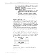
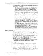
Страница 25: ...to no more than 0 25 N m 2 2 in lbs torque Failure to follow these guidelines may result in damage to your connector Wire the module using the following images which explain the layout of each 2 row 18 pin terminal block and the associated wiring diagrams for the various input signals and the two modules RTB1 Name 1 IN0 2 IN0 3 IN1 4 IN1 5 IN2 6 IN2 7 IN3 8 IN3 9 IN4 10 IN4 11 IN5 12 IN5 13 IN6 14...

Страница 26: ...e 1 IN0 2 IN0 3 IN1 4 IN1 5 IN2 6 IN2 7 IN3 8 IN3 9 IN4 10 IN4 11 IN5 12 IN5 13 IN6 14 IN6 15 IN7 16 IN7 17 CJC1 18 CJC1 RTB2 Name 19 CJC2 20 CJC2 21 IN8 22 IN8 23 IN9 24 IN9 25 IN10 26 IN10 27 IN11 28 IN11 29 IN12 30 IN12 31 IN13 32 IN13 33 IN14 34 IN14 35 IN15 36 IN15 2085 IT16 SC ...

Страница 27: ...7 Return 34 NC 17 CJC1 CJC 1 Positive Input Potted thermistor on this side 35 NC 18 CJC1 CJC 1 Return 36 NC 2085 IT16 SC Terminal Block Input signal descriptions are as follows RTB1 Name Description RTB2 Name Description 1 IN0 Ch0 Positive input 19 CJC2 CJC 2 Positive Input Potted thermistor on this side 2 IN0 Ch0 Return 20 CJC2 CJC 2 Return 3 IN1 Ch1 Positive input 21 IN8 Ch8 Positive input 4 IN1...

Страница 28: ...Rev A RTB1 Name Description RTB2 Name Description 15 IN7 Ch7 Positive input 33 IN14 Ch14 Positive input 16 IN7 Ch7 Return 34 IN14 Ch14 Return 17 CJC1 CJC 1 Positive Input Potted thermistor on this side 35 IN15 Ch15 Positive input 18 CJC1 CJC 1 Return 36 IN15 Ch15 Return ...

Страница 29: ...on software utility that you may use to provide configuration settings to the profile You then send the configuration setup to the module Your controller firmware must be at v 9 011 and above as well The Micro850 870 Controller Bus master subsystem is located at the left end of the bus This subsystem is comprised of Micro800 Controller Micro800 Plug in I O Modules 2085 ECR Bus Terminator Optional ...

Страница 30: ...sion is released see Appendix A about how to manually import a module AOP to CCW 2085 IT8 SC IT16 SC 8 Channel 16 Channel TC mV Analog Input Module Micro850 870 Controller Micro800 Expansion I O Modules PC Workstation with CCW Program and 2085 IT8 SC or 2085 IT16 SC RAMPP file Thermocouple Type J N T K E S R C B 2080 Expansion I O Modules Micro800 Expansion I O Module Backplane 2080 Plug In I O mo...

Страница 31: ...le Profile Tool option from the CCW Tools menu 2 When prompted by Windows User Account Control to confirm that you wish to run the program click the Yes button If necessary confirm with the Windows operating system that you wish to run the software The Module Profile Tool dialog appears 3 Select the row showing the module catalog name 2085 IT8 SC or 2085 IT16 SC and then click the View button The ...

Страница 32: ...4 Chapter 3 Configuring the 2085 IT8 SC IT 16 SC Using CCW User s Manual Pub 0300322 01 Rev A 2085 IT8 SC profile 2085 IT16 SC profile The first tab of the window provides the module identity information ...

Страница 33: ...iew software language availability module description and a help file for the module click the Resources tab The Resources tab appears 2085 IT8 SC 2085 IT16 SC The window lists the language chosen for the module and the module description You may also use this tab to access the help file provided for the module 5 To view default configuration information click the Default Configuration tab ...

Страница 34: ...indicates that the module AOP provides the service for launching the MCC utility to help you configure your module More information is described in Setting Configuration Parameters Using MCC later in this section Section 3 3 CCW Configuration Tab Before you start if needed install the latest version of Rockwell Automation s Connected Components Workbench CCW Standard Edition ...

Страница 35: ...ee Appendix A For Version 11 00 00 and later the module is already available as a selection from the CCW Expansion Modules drop down menu To add the module to your project and see its configuration parameters on the CCW configuration tab 1 From your CCW project load the module AOP to a first Available slot from the Expansion Modules drop down list 2085 IT8 SC is used as the example here 2 Once the...

Страница 36: ...b click the Configuration option Maximum Length Shows maximum number of words available Each word is 16 bit Configuration The textbox lists out the whole module configuration value Radix The drop down menu contains the following number formats for indicating module configuration value Options are Hex Default option Characters represented as hexadecimal Example 0 7FFF as 32767 in decimal format ...

Страница 37: ...Inc You download the utility from the Spectrum Controls website at www spectrumcontrols com NOTE It is recommended that when you generate your configuration that you use the Binary Radix selection If you choose the Decimal Radix the utility is unable to work with negative values To use the MCC utility 1 The first time you configure a Spectrum Controls 2085 analog module you must provide the file p...

Страница 38: ... Using CCW User s Manual Pub 0300322 01 Rev A Example C Program Files x86 Rockwell Automation CCW SpectrumTool 3 To run the tool click Launch The Module Config Converter dialog appears 4 Select the 2085 IT8 SC module from the drop down menu and click OK ...

Страница 39: ...very configuration bit Chan Lists number of input channel from 0 to 7 or 0 to 15 for IT16 Enable Specifies whether to enable use of this channel Enabled by default checkbox enabled Input Type Specifies which input type to use Select type from drop down list Type J TC input is default Data Format Specifies which data format to use for reporting input values Default is Engineering Units X1 Temp Unit...

Страница 40: ...whether a warning on under or over range detection from user defined values is turned on for the channel disabled or enabled for both alarm and latch Process Alarm High Specify over range value of a user defined value for the module to monitor Process Alarm Low Specify under range value of a user defined pair of high and low values for the module to monitor Channel Bias Specifies individual channe...

Страница 41: ...nerated settings into the textbox of the CCW Configuration tab have the textbox visible on the monitor screen and then click Copy to CCW button5 The utility copies the configuration settings and shows it inside the textbox 5 It is recommended that before manually or automatically pasting your configuration settings to the textbox of the CCW Configuration tab be sure to select the Hex Radix indicat...

Страница 42: ...the Configuration Assembly There is no input data communication and no signal outputting before the controller goes into run mode The initial configuration assumes a default configuration of Type J TC and the 17 Hz filter using the Engineering Unit 1 setup Module Identity The following values will be stored in the Vendor ID Product_Type Product_Code Series_Rev and Mod_Features arrays Parameter 208...

Страница 43: ...n Bits Config 28 Ch7 Configuration Bits Ch7 Process Alarm High Value Config 29 Ch7 Process Alarm High Value Ch7 Process Alarm Low Value Config 30 Ch7 Process Alarm Low Value Ch7 Channel Bias Value Config 31 Ch7 Channel Bias Value Unused Config 32 Ch8 Configuration Bits Config 33 Ch8 Process Alarm High Value Config 34 Ch8 Process Alarm Low Value Config 35 Ch8 Channel Bias Value Ch9 to Ch14 Configur...

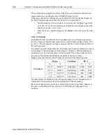
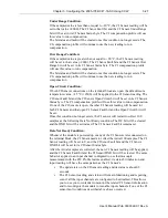
Страница 44: ...e only when the Input Type of the selected input channel is configured to use Thermocouple type 2 The channel scan rate of the selected input channel will mix with the CJ Sensor sampling rate if the channel is configured to use Thermocouple type and the CJ Compensation Weighted Profile option is configured to enable with the provided profile 3 5 7 Channel Configuration Values Each 2085 IT8 SC and ...

Страница 45: ...te Low Byte Bits 15 14 13 12 11 10 9 8 7 6 5 4 3 2 1 0 Ch0 Data AI_00 Signed INT Ch1 Data AI_01 Signed INT Ch2 Data AI_02 Signed INT Ch3 Data AI_03 Signed INT Ch4 Data AI_04 Signed INT Ch5 Data AI_05 Signed INT Ch6 Data AI_06 Signed INT Ch7 Data AI_07 Signed INT Ch 1 0 Status AI_08 DNR OC OR UR PAH PAL ADC FT1 DNR OC OR UR PAH PAL ADC FT0 Ch 3 2 Status AI_09 DNR OC OR UR PAH PAL ADC FT3 DNR OC OR ...

Страница 46: ... 0 Status AI_16 DNR OC OR UR PA H PA L AD C FT1 DNR OC OR UR PA H PA L AD C FT0 Ch 3 2 Status AI_17 DNR OC OR UR PA H PAL AD C FT3 DNR OC OR UR PA H PAL AD C FT2 Ch 5 4 Status AI_18 DNR OC OR UR PA H PAL AD C FT5 DNR OC OR UR PA H PAL AD C FT4 Ch 7 6 Status AI_19 DNR OC OR UR PA H PAL AD C FT7 DNR OC OR UR PA H PAL AD C FT6 Ch 9 8 Status AI_20 DNR OC OR UR PA H PAL AD C FT9 DNR OC OR UR PA H PAL A...

Страница 47: ... ADC n ADC Communication Failure or PGA Connection Failure When set to 1 indicates there is a channel ADC communication failure or PGA connection error This is a hardware fault 10 2 PAL n Process Alarm Low When set to 1 indicates the channel input value is less than or equal to the user defined Process Alarm Low Value in the configuration table 11 3 PAH n Process Alarm High When set to 1 indicates...

Страница 48: ...range 11 3 OC x Open Circuit When set to 1 indicates the CJ Sensor connection on the terminal block is open 12 4 DNR x Data Not Ready When set to 1 the module is initializing sampled data 5 6 7 Unused Bits masked as Unused are set to 0 13 CAL Invalid Cal Data The stored calibration data or checksum is corrupt or invalid The module must be factory calibrated before it will operate normally 14 SN In...

Страница 49: ... on clearing the Low and High Process Alarm Latches for 8 channels a group To operate the control bits see the Process Alarm and Latching feature Tag Name for 2085 IT8 SC 1 Word Word Index Tag Name for 2085 IT16 SC 2 Words Ch 7 0 Clear High Low Process Alarm Latch AO_00 Ch 7 0 Clear High Low Process Alarm Latch Unused AO_01 Ch 15 8 Clear High Low Process Alarm Latch 3 5 13 Output Bit Allocation Pr...

Страница 50: ...r options for channel input display Index Data Format 0 Engineering Unit 1 1 Engineering Unit 10 2 Raw Proportional 3 Percentage Full Scale The maximum range to display a measured input data in the input table is from 32768 to 32767 as a signed 16 bit integer The actual range will be scaled to fit the selected Input Type For example the valid range for Type B Thermocouple is from 300 C to 182 0 C ...

Страница 51: ...ange 4540 2700 454 270 32768 0 454 0 270 0 Low Limit 4540 2700 454 270 32768 0 T 752 0 400 0 High Limit 7520 4000 752 400 32767 10000 752 0 400 0 High Range 7520 4000 752 400 32767 10000 454 0 270 0 Low Range 4540 2700 454 270 32768 0 454 0 270 0 Low Limit 4540 2700 454 270 32768 0 E 1832 0 1000 0 High Limit 18320 10000 1832 1000 32767 10000 1832 0 1000 0 High Range 18320 10000 1832 1000 32767 100...

Страница 52: ...C Low Limit 10500 1050 32768 250 1 Type B and C thermocouples cannot be represented in engineering units 1 F above 3276 7 F Software treats it as an over range error 2 When millivolts are selected the temperature setting is ignored Analog input data is the same for either C or F selection The firmware will report a configuration error if an invalid range value is entered in the configuration table...

Страница 53: ...erted to temperature in C based on the thermocouple curve specification 𝑏 is the offset 𝑈𝑠𝑒𝑟 𝐿𝑜𝑤 𝐿𝑖𝑚𝑖𝑡 𝑚 𝐴𝑐𝑡𝑢𝑎𝑙 𝐿𝑜𝑤 𝐿𝑖𝑚𝑖𝑡 In above example 𝑏 3000 10 300 0 so if the thermocouple measured 10 0 degrees C then the display of the reading for EU 1 is 10 0 10 0 Channel Bias 𝐶ℎ𝑎𝑛𝑛𝑒𝑙 𝐵𝑖𝑎𝑠 is an offset in integer format The Channel Bias value is only applied to the raw measured value It will not be applied...

Страница 54: ...ge is from 20 ºC to 90 ºC The temperature reading is measured by the 12 bit resolution ADC on the main processor The Data Type in the input table used to display the CJ Sensor reading is a signed 16 bit integer The valid range is scaled down at 2000 to 9000 indicating its resolution up to two decimal places in Celsius units The sensor limits are set to the same as the minimum and maximum points of...

Страница 55: ...s value to run compensation If one of the CJ Sensors is open the other CJ Sensor reading will be used for both CJ Sensors and that open CJ Sensor Fault bit and the Open Circuit bit will be set Once this condition no longer exists the CJ sensor will restart to collect 100 samples as the following Data Not Ready condition The OC bit will be cleared and the DNR bit will be set instead The CJ Sensor F...

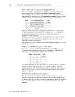
Страница 56: ...ermocouple profile range the cold junction compensation will also be skipped If an invalid CJC Profile is entered in the configuration table the module reports a configuration error 3 6 8 Input ADC Filter Frequencies Description The modules use an input ADC digital filter that provides high frequency noise rejection for each input signal The filter for each channel is programmable allowing you to ...

Страница 57: ...t will be set For the Downscale option the channel input reading will be set to the low limit point based on the selected Input Type and Data Format The Channel Fault bit and the OC bit will be set For the Zero option the channel input reading will be set to 0 no matter what Input Type and Data Format is configured The Channel Fault bit and the OC bit will be set For the Disable option an open cir...

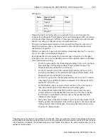
Страница 58: ...lso be used as an Over or Under Input Type Limit alarm Once the channel input reading is equal to or greater less than your user defined value the corresponding channel Process Alarm status bit in the input table will be set The lowest value for the Process Alarm Low Value that can be set is the Data Type low limit 32768 if the low limit of the selected Input Type is lower than that value The same...

Страница 59: ...ration table The module will automatically clear the Process Alarm High status bit in the Channel Status byte and its Channel Fault bit when the channel input reading is less than the user defined Process Alarm High Value entered in the configuration table If Option 2 is selected The latch functions as follows Once the channel Process Alarm Low or High status bit is set as latched it will not be c...

Страница 60: ...imum point of the selected Input Type range The channel Under or Over range status bits will also be cleared when the channel input reading is greater or less than the low or high limit of the Data Type if the minimum or maximum point of the selected Input Type range is beyond the data limits Section 3 8 ADC Alarm When each input channel is acquiring its channel data in sequence on the correspondi...

Страница 61: ... detection enable bits The following table indicates maximum module date rate with all channels enabled and all channel open circuit detection bits enabled ADC Filter Selection Scan Rate Per Channel Number of Channels Total Module Scan Rate 17 Hz 139 23 16 1296 4 Hz 499 23 16 4176 62 Hz 51 23 16 592 470 Hz 23 23 16 368 3 9 1 Module Specific Hardware Errors A Micro850 or 870 PLC can generate a seri...

Страница 62: ...F Invalid Process Alarm Value Check the Process Alarm Low Value and Process Alarm High Value for legal ranges If the module receives any of the following illegal data this error is detected Exception for this error is both PALV and PAHV are zero PALV greater than or equal to PAHV OR PAHV greater than Input Type High Limit OR PALV greater than Input Type Low Limit PALV is the Process Alarm Low Valu...

Страница 63: ...se Authorization form required for all product returns For further information or assistance please contact your local distributor or call the Spectrum Controls Technical Support at For Rockwell Automation Compatible I O Products USA 440 646 6900 United Kingdom 01908 635230 Australia 1800 809 929 Mexico 001 888 365 8677 Brazil 55 11 3618 8800 Europe 49 211 41553 630 Section 3 11 Declaration of Con...

Страница 64: ...3 36 Chapter 3 Configuring the 2085 IT8 SC IT 16 SC Using CCW User s Manual Pub 0300322 01 Rev A ...

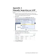
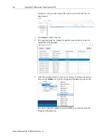
Страница 65: ...Controls website https www spectrumcontrols com and save the file to a local folder on your computer normally the Downloads folder 2 Run CCW 3 From the Tools menu select the Module Profile Tool option 4 When prompted by Windows User Account Control to confirm that you wish to run the program click Yes button The Module Profile Tool 2 0 window appears 5 Click the Import button 6 An Open dialog appe...

Страница 66: ...d 7 Click Open to import the file 8 The program loads the rampp file and informs you that you need to restart the CCW program 9 After the program restarts create a new project or reload your project Select an Available slot from the Expansion Modules drop down list The newly imported module is now available as a selection from the Expansion Modules list ...

Страница 67: ...pecifications 1 3 Hardware Features 1 9 Hazardous Location 2 2 Hex option 3 8 Input ADC Filter Frequencies description 3 28 Input Type 1 2 field 3 11 Launch MCC utility 3 9 LED indicators 1 9 Maximum Length information 3 8 Minimum spacing 2 4 Module configuration errors 3 34 hardware errors 3 33 mounting 2 3 Overview 1 1 Module Catalog Name 3 7 Module Identity 3 14 Mounting module 2 3 Noise 2 3 Op...

Страница 68: ...I 2 Index User s Manual Pub 0300322 01 Rev A ...

Страница 69: ...User s Manual Pub 0300322 01 Rev A ...

Страница 70: ...cations subject to change without notice The Encompass logo and Micro800 are trademarks of Rockwell Automation Corporate Headquarters Spectrum Controls Inc 1705 132nd Ave NE Bellevue WA 98005 Fax 425 641 9473 Tel 425 746 9481 Web Site www spectrumcontrols com E mail spectrum spectrumcontrols com ...

Отзывы: