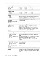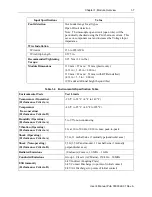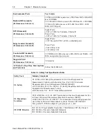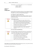
Chapter 2: Installation and Wiring
2-5
User’s Manual Pub. 0300322-01 Rev. A
NOTE
•
This equipment is considered Group 1, Class A industrial
equipment according to IEC/CISPR 11. Without appropriate
precautions, there may be difficulties with electromagnetic
compatibility in residential and other environments due to
conducted and radiated disturbance.
•
Be careful when stripping wires. Wire fragments that fall into the
controller could cause damage. Once wiring is complete, make
sure the controller is free of all metal fragments before removing
the protective debris strip.
•
Do not wire more than 2 conductors on any single terminal.
•
If you insert or remove the expansion I/O module while power is
on, an electrical arc can occur. This could cause an explosion in
hazardous location installations. Be sure that power is removed or
the area is nonhazardous before proceeding.
•
Cable connection lengths are currently 1 foot, and 1 meter.
2.4.4
Insert Module Next to the Controller
Follow the instructions to insert and secure the expansion I/O module to the
controller:
NOTE
The module expansion may only be mounted horizontally.
NOTE
For environments with greater vibration and shock concerns, use the panel
mounting method, instead of DIN rail mounting.
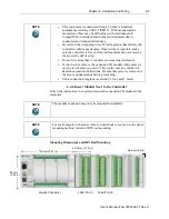
Mounting Dimensions and DIN Rail Mounting
150 mm (5.91 in.)
44.5 mm (1.75 in.)
Micro850 Controller
2085-IT8-SC
Bus terminator
89 mm
(3.50 in.)
2085-IT16-SC

