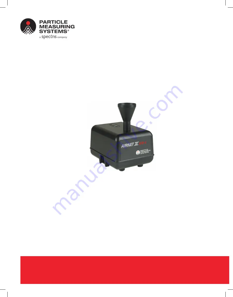
Airnet® II 4-CH Particle Sensors
MODELS 201-4, 301-4, 310-4, 501-4, 510-4
P/N 1000016470
OPERATIONS MANUAL
Without measurement there is no control
Страница 1: ...Airnet II 4 CH Particle Sensors MODELS 201 4 301 4 310 4 501 4 510 4 P N 1000016470 OPERATIONS MANUAL Without measurement there is no control ...
Страница 2: ...ce pmeasuring com GERMANY T 49 6151 6671 632 E pmsgermany pmeasuring com ITALY T 39 06 9053 0130 E pmssrl pmeasuring com JAPAN T 81 3 5298 8175 E pmsjapan pmeasuring com KOREA T 82 31 286 5790 E pmskorea pmeasuring com MEXICO T 52 55 2271 5106 E pmsmexico pmeasuring com NORDIC T 45 707 028 55 E pmsnordic pmeasuring com PUERTO RICO T 1 787 718 9096 E pmspuertorico pmeasuring com SINGAPORE T 65 6496...
Страница 3: ...e Measuring Systems The information contained in this document is subject to change without notice Quality Statement The Quality Policy of Particle Measuring Systems is to strive to meet or exceed the needs and expectations of our customers and to align the activities of all employees with the common focus of customer satisfaction through continuous improvement in the quality of our products and s...
Страница 4: ...ith this information WARNING A warning in the text is used to notify the user of the potential for bodily injury or death CAUTION A caution in the text is used to highlight an item that if not done or incorrectly done could damage the instrument and or any materials or devices affected by the instrument NOTICE A notice in the text is an instructional communication regarding requirements or policie...
Страница 5: ...istributor s Name Particle Measuring Systems S R L Distributor s Address Via di Grotte Portella 34 00044 Frascati Roma ITALY Distributor s Telephone FAX 39 06 90530130 39 06 9051315 Type of Equipment Particle Monitoring Model No Airnet II 4 Channel 201 4 301 4 310 4 501 4 510 4 I the undersigned hereby declare that the equipment specified above conforms to the above Directive s and Standard s Sign...
Страница 6: ...Installation 2 1 Unpacking 2 1 Shipping List 2 1 Items You Need to Provide 2 2 Installation 2 2 Automated Laser Power Control 2 2 Detector Board Monitor 2 2 Selecting a Location 2 3 Positioning or Mounting the Unit 2 4 Powering the Sensor from 24 VDC 2 5 Powering the Sensor from Power over Ethernet PoE 2 5 Connecting the Power Supply 2 6 Connecting the Sample and Vacuum Tubing 2 6 Chapter 3 Config...
Страница 7: ...pter 5 Maintenance and Performance Checks 5 1 Cleaning the Sensor s Housing 5 1 Cable Connectors 5 1 Performance Checks 5 1 Airflow Rate Check 5 1 Background Count Check 5 2 Chapter 6 Troubleshooting 6 1 Troubleshooting Matrix 6 1 Airflow Rate Errors 6 2 Isolating and Repairing Leaks 6 2 Particle Induced Counts 6 3 Transient Induced Counts 6 3 Appendix A TCP IP Protocol A Brief Overview A 1 TCP IP...
Страница 8: ...tents Airnet II 4 Channel Particle Sensors Operations Manual vii ADVERTENCIA C 1 Hazard Symbols C 2 Symboles de risque C 2 Warnschilder C 2 Simboli di pericolo C 3 Simbolos de peligro C 3 Appendix D 㦘㹡㒥㦘 䤓䓸德 侯 D 1 ...
Страница 9: ...viii Airnet II 4 Channel Particle Sensors Operations Manual Table of Contents This page is intentionally left blank ...
Страница 10: ...ng Bracket P N MP8876 2 4 Figure 2 2 S Type Mounting Bracket P N MP8877 2 4 Figure 2 3 L Type Mounting Bracket P N MP8865 2 4 Figure 2 4 Dovetail Mounting Bracket P N MP7872 2 4 Figure 2 5 24 VDC Power Connector 2 5 Chapter 3 Configuring for Ethernet 3 1 Chapter 4 4 20 mA Signal Configuration Operation 4 1 Chapter 5 Maintenance and Performance Checks 5 1 Chapter 6 Troubleshooting 6 1 Appendix A TC...
Страница 11: ...x Airnet II 4 Channel Particle Sensors Operations Manual List of Figures This page is intentionally left blank ...
Страница 12: ...Summary of 4 20 mA Channel thresholds 4 1 Table 4 2 4 20 mA Channel thresholds 4 1 Table 4 3 4 20 mA factory preset status levels 4 2 Table 4 4 RS 232 pinouts RJ 11 Connectors on the Airnet II 4 Channel particle sensor 4 2 Table 4 5 Terminal emulator communications parameters 4 3 Table 4 6 Airnet II 4 Channel particle sensor 4 20 mA connector pins 4 6 Chapter 5 Maintenance and Performance Checks 5...
Страница 13: ...xii Airnet II 4 Channel Particle Sensors Operations Manual List of Tables Appendix D 㦘㹡㒥㦘 䤓䓸德 侯 D 1 ...
Страница 14: ...l particle sensors communicate by means of Ethernet with Facility Net1 a software package that stores and displays particle data and allows the user to control the Airnet II 4 Channel particle sensor The Airnet II 4 Channel particle sensor models can also communicate via Modbus TCP via the Ethernet connection All Airnet II 4 Channel sensors can communicate via Modbus TCP when that feature is activ...
Страница 15: ... sensor Class I Laser Product The Airnet II 4 Channel particle sensors are Class 1 laser products WARNING This instrument is a Class l laser product a Use of controls adjustments or performance of procedures other than those specified here may result in hazardous radiation exposure a National Center for Device and Radiological Health formerly BRH ...
Страница 16: ...ilityNet salarm settings The failure state depends upon how the particle sensor is configured in Facility Net When disconnected from Facility Net you can set the unit to run the Status LED two distinct ways Set the Status LED to flash green when disconnected Set the Status LED to represent the internal state of the flow and or laser status indication The Status LED will normally remain green excep...
Страница 17: ...VacuumSource Thebarbedfittingallowsasourceofvacuum 12 in Hg tobe supplied to the unit Calibration Three SMB connectors are available for calibrations only and are not used for system operation Optional 24 VDC Input 4 20 mA Output The 12 pin Molex connector allows a 24 VDC input power supply to power the unit and or outputs scaled 4 20 mA signals that transmit the following Channel 1 2 3 and 4 part...
Страница 18: ...level counts m3 70 7 70 7 7 07 70 7 7 07 Counting efficiency Meets ISO 21501 4 50 20 for most sensitive channel 100 10 at 1 5 to 2 0 times channel one size Flow system External vacuum Vacuum source 12 in Hg Material chassis Polycarbonate PC Dimensions L W H 5 3 3 6 3 8 in 13 5 8 9 9 6 cm Weight 1 6 lb 0 73 kg Power PoE 48 VDC 0 25 A or optional 24 VDC 0 5 A Optional POE Power Injector Input 100 24...
Страница 19: ... conditions 5 95 RH non condensing Storage and transportation temperature 10 50 C 14 122 F Maximum altitude 6 562 ft 2000 m Installation requirements Indoor use only Pollution degree 2 Over voltage category I Ordinary protection not protected against harmful ingress of moisture Optional POE Power Injector Over voltage Category II Class I Equipment Electrical earth ground from the mains power sourc...
Страница 20: ...nties may not apply if return shipping containers are inadequate Shipping List Table 2 1 Airnet II 4 Channel particle sensor shipping list Part Name Quantity Isokinetic air sampler probe 1 L Type mounting bracket or one of three alternate bracketsa a You must order alternate brackets in advance 1 Phone jack cable RS 232b b Used only for configuring the Airnet II 4 Channel particle sensor 1 Operati...
Страница 21: ...cting a Communications Cable Connecting Sample Tubing or Sample Probe as applicable Attaching Vacuum Tubing Automated Laser Power Control AirnetII4 Channelparticlesensorunitscontainanautomatedlaserpowercontrolthat automatically shuts off the laser power after 10 seconds of continuous bad flow flow rate that is 15 of the specified flow rate The laser power is restored after 10 seconds of continuous...
Страница 22: ... ensure that the sampling probe is pointed INTO the airflow you want to monitor Accessibility The unit should be readily accessible for connecting and disconnecting cables and so on Interference with existing equipment The unit should not interfere with access to existing or known future equipment installations Visibility The unit s front and top panels should be visible from a reasonable position...
Страница 23: ...surface with a mounting bracket that attaches to the bottom of the sensor s chassis with machine screws provided The Airnet II 4 Channel particle sensor is attached to a chosen surface with one of the following four types of mounting bracket A horizontal mounting bracket for attaching to a horizontal surface An S shaped mounting bracket for attachment to a horizontal surface An L shaped mounting b...
Страница 24: ... supply wiring is sized 18 AWG 0 75 mm2 minimum and the supply is current limited to 8 A maximum or fused at 5A maximum If using a local power source a receptacle and crimp pins are available that attach to the ends of the power cable The crimp pins are then inserted into the provided 12 pin Molex Micro Fit receptacle Figure 2 5 24 VDC Power Connector Powering the Sensor from Power over Ethernet P...
Страница 25: ... and power supply are all right the unit may be faulty Connecting the Sample and Vacuum Tubing The plumbing connections are the following NOTE After completing the cabling for the 12 pin Molex Micro Fit connector for 24 VDC or 4 20 mA install the ferrite as close as practical to the connector that will still allow you to insert and or remove the connector in the future Sample inlet The sample inle...
Страница 26: ...nalinformation see Appendix B Modbus Protocol When to Configure the Sensor If it will be difficult or impossible to take a computer to the Airnet II 4 Channel particle sensor after installation it should be configured before installation Ifaccesstothesensorafterinstallationwillbeeasy youcanconfigurethesensoreither before or after installation Required Hardware and Software RS 232 cable Computer lo...
Страница 27: ...lation software using the provided RS 232 cable 2 Start the terminal emulation software and proceed to the COM 1 parameters dialog box 3 Set the following communication parameters Table 3 1 RS 232 pin outs RJ 11 jack Pin 1 DSR Pin 2 Transmit Pin 3 Receive Pin 4 RTS Pin 5 CTS Pin 6 GND NOTE Pins 1 4 and Pin 5 are shorted together CAUTION As with any network capable software do not attempt to connec...
Страница 28: ...et mask Gateway NTP address Queue size if used with Facility Net or Modbus Connection status Operational mode Set ip aaa bbb ccc ddd The IP address is used when communicating across networks This command sets the address in the form of aaa bbb ccc ddd Each three digit series is a value of 0 255 separated by a period character An example of a valid IP address is 010 255 000 060 Set mas k aaa bbb cc...
Страница 29: ...ng this parameter automatically saves the value and reboots the sensor The value of x can be set anywhere between 1 and 1440 The queue size to enter depends on the specific application In general the value should be made large enough to minimize data loss when disconnected but not so large as to create significant delays in the reception of real time data when reconnected When a data queue size is...
Страница 30: ...hanges You must send this command after setting up the instrument or your parameters will be lost when the sensor is de energized TCP IP Settings for the Airnet II 4 Channel Particle Sensor Viewing Configuration Settings Type sta tus and press the Enter key to display the Airnet II 4 Channel particle sensor s configuration settings software version and connection status If this command does not pr...
Страница 31: ...best with a CAT 5 UTP cable Other types of Ethernet cable may produce excess noise Your Information Systems Manager Network Administrator or other appropriate computer support personnel may be able to assist in procuring a cable or fabricating a custom length cable After physically attaching the Airnet II 4 Channel particle sensor to a network Facility Net or Modbus TCP client will find the sensor...
Страница 32: ...unded load of 400 ohms or less All grounds are common and are common to the internal analog ground of the sensor NOTE The Airnet II 4 Channel particle sensor can output data to Facility Net software while it also outputs 4 20 mA signals to a SCADA system Table 4 1 Summary of 4 20 mA Channel thresholds First signal output Channel 1 particle data Second signal output Channel 2 particle data Third si...
Страница 33: ...re and Software Computer loaded with HyperTerminal or other terminal emulation software RS 232 configuration cable provided in your shipment Wiring for this cable is as follows Table 4 3 4 20 mA factory preset status levels Current Flow Status Laser Status 8 mA OK OK 12 mA OK Bad 16 mA Bad OK 20 mA Bad Bad NOTE The following information assumes that the operator has a working knowledge of terminal...
Страница 34: ...s to set the parameters for your 4 20 mA application Record your parameters for future reference A list of available commands are described in the following section Viewing Configuration Settings Typing sta tus and then pressing the Enter key results in a display of the Airnet II 4 Channel particle sensor s configuration settings software version and connection status If typing status or and then ...
Страница 35: ...or the first four configurable 4 20 mA outputs if that option is available If n equals 1 the data is cumulative and represents the number of particles detected that are larger than the size specified for the channels If n equals 0 the data is differential and represents the number of particles detected that are between the sizes specified for each output channel set eos n If n is set to 1 then the...
Страница 36: ...for the index of the 4 20 mA output to be adjusted Output Channels 1 5 are indexed 0 4 The offset and scale factors for the selected output will be set to 0 and 1 respectively 3 The sensor will now apply 4 mA to the selected output The operator will be prompted to enter the actual reading as measured by the current meter This will calculate the appropriate offset factor to be applied to that outpu...
Страница 37: ...cle sensor 4 20 mA connector pins 1 Aftercompletingthecablingforthe12 pinMolexMicroFitconnector installthe ferrite as close as practical to the connector that will still allow you to insert and or remove the connector in the future 2 Connect the cable from the Airnet II 4 Channel particle sensor s 4 20 mA output to the data collection system s input 3 Set up the data collection system to correctly...
Страница 38: ...nections are somewhat fragile If a connector is damaged be careful not to aggravate the problem by forcing a cable into a damaged connector A Particle Measuring Systems Service Representative can repair or replace damaged connectors Performance Checks Complete the following procedures to verify that your instrument is operating properly Airflow Rate Check The sample flow is factory set using a cri...
Страница 39: ... exception the only way to verify externally induced counts is to perform this procedure To perform this procedure you will need an absolute filter rated at less than 0 2 micron effective to 0 1 micron in air To perform a background count check 1 Locate the Airnet II 4 Channel particle sensor to where it will normally be used 2 Remove the isokinetic sample horn 3 Place the 0 2 micron absolute filt...
Страница 40: ...r power including any power strips or surge protectors Power supply faulty Try a different power supply If using PoE Verify power is being supplied Communications not established Facility Net displays Communications Error Unable to view data from working sensor Ethernet cable problem Replace the Ethernet cable that connects the sensor to an Ethernet hub Unit not configured correctly Re configure t...
Страница 41: ...ample flow rate If the flow rate is still low after determining that there is sufficient vacuum perform the following procedure Isolating and Repairing Leaks To isolate and repair leaks 1 Remove the top and bottom halves of the instrument 2 Run samples 3 While a sample is running use a bulb syringe to blow a small amount of smoke around the possible leak paths and watch for an increase in the numb...
Страница 42: ...horn 1 Remove both the isokinetic sampling horn and jet and flush both with a cleaning solvent alcohol acetone and so on 2 Dry the isokinetic sampling horn and the jet using clean pressurized air 3 Replace the jet and horn Make sure to line up the alignment indicators Transient Induced Counts Line transients RFI or EMI noise counts are generally subtle and unique to a certain installation If these...
Страница 43: ...6 4 Airnet II 4 Channel Particle Sensors Operations Manual Chapter 6 Troubleshooting Transient Induced Counts This page is intentionally left blank ...
Страница 44: ...col for Microsoft Windows for Workgroups 3 11 includes a PING function that must be run from a Windows DOS window To use the Windows TCP IP PING 1 With Windows running open a DOS window by double clicking on the MS DOS Prompt icon 2 At the DOS prompt type PING IP ADDRESS using the address of the device for which you wish to test your computer s LAN communications The PING utility will report wheth...
Страница 45: ...A 2 Airnet II 4 Channel Particle Sensors Operations Manual Appendix A TCP IP Protocol A Brief Overview Ping This page is intentionally left blank ...
Страница 46: ...alues These values can be interpreted as integer representations of floating point numberswithafixedscalingfactororasIEEE 754floatingpointrepresentationsofthat value Refer to the register map to determine which register pairs have this feature applied This setting can be made in the setup interface and saved in non volatile storage or set real time via a coil 1 Input registers Read only informatio...
Страница 47: ...host can use this to check for data availability for example The Device State register is a single register in which the LSByte is a state value and the MSByte is an associated sub state value The time stamp set of registers is a time_t value The Data Packet Status is two registers for growth 3 bits are used Flow Rate and Volume are in CF These can be read either as integer values with fixed scale...
Страница 48: ...2 Size low nanometers Type 30021 ushort Channel 3 Size high nanometers 30022 ushort Channel 3 Size low nanometers Type or N A 30023 ushort Channel 4 Size high nanometers 30024 ushort Channel 4 Size low nanometers Type or N A Table B 2 Input register data packet Input Registers Description Data Packet Comment Notes 30201 ushort Calibration Date Month Calibration Date 30202 ushort Calibration Date D...
Страница 49: ...224 ushort Volume high Volume 10 Scale cf Float Mode 30225 ushort Volume low Volume 10 Scale cf Float Mode 30226 ushort Location Location value n a 30227 ushort Number Particle Channels Variable across types 2 or 4 fixed 30228 ushort Number Analog Channels Variable across types 0 30229 ushort Particle Channel 1 high Cumulative Raw Ch1 30230 ushort Particle Channel 1 low Cumulative Raw Ch1 30231 us...
Страница 50: ... It will start a sequence of samples if the repeat count has been set Read Write 1 Sampling Enabled 0 Sampling Disabled 2 The data available coil is used to both inform the host that data is now available and to delete the next queued data packet if desired Read 1 Data Available 0 No Data Available Write 0 Delete queued data element 3 The data clear coil will delete all data in the queue Write 1 D...
Страница 51: ...ime data only Since the queue is circular the next sample will replace the single one in the queue Queued data will always be available even when not sampling If there is no data available the input registers will yield zeros This is done instead of generating an execution exception so that the customer can simply read the data packet along with the Device Status in one command Table B 4 Coils Coi...
Страница 52: ...01 Data Collection Matches the common coil settings 0x0002 Data Available 0x0004 Data Clear 0x0008 Reset 0x0010 Green Status 0x0020 Red Status 0x0040 External Alarm 0x0080 IEEE Float mode Device State Entries LSByte 0 Idle 1 Sampling 2 Maintenance 3 Error Device SubState Entries MSByte 0 Idle n a 0 Sampling n a 1 Sampling Tare 0 Maintenance n a 1 Maintenance Calibration 0 Error n a Data Packet Sta...
Страница 53: ...B 8 Airnet II 4 Channel Particle Sensors Operations Manual Appendix B Modbus Protocol Associated Values for Specific Registry Entries This page is intentionally left blank ...
Страница 54: ...erprodukt der Klasse 1 welches den Normen US 21 CFR 1040 10 und EN 60825 1 entspricht Das Justieren der Lasereinheit das Verändern des Gerätes oder Einsatzbereiche die nicht den Vorgaben dieser Anleitung für das Gerät entsprechen können dazu führen dass gefährliches Laserlicht austritt ATTENZIONE Lo strumento è classificato come prodotto laser di Classe 1 e rispetta l US 21 CFR 1040 10 e l EN 6082...
Страница 55: ...nschilder Die an dem Gerat angebrachten Warnschilder haben folgende Bedeutungen Symbol Nature of Hazard Attention consult accompanying documents Dangerous High Voltage Warning Laser radiation Avoid exposure to beam Symbole Nature du risque Attention consulter les documents d accompagnement Danger Electricite Avertissement Rayonnement laser Éviter toute exposition au faisceau Symbol Gefahrenart Ach...
Страница 56: ...rumenti il seguente Simbolos de peligro Los simbolos de peligro que aparecen en el equipo significan Simbolo Natura del pericolo Attenzione Consultare i documenti allegati Tensione Pericolosa Avvertenza Radiazione laser Evitare l esposizione ai raggi Símbolo Naturaleza del Peligro Atención consultar los documentos adjuntos Peligro alto voltaje Advertencia Radiación láser Evite exponerse al rayo ...
Страница 57: ...C 4 Airnet II 4 Channel Particle Sensors Operations Manual Appendix C International Precautions Simbolos de peligro This page is intentionally left blank ...
Страница 58: ... 䤓䓸德 侯 Part Name 捷ↅ 䱿 㦘㹡㒥㦘 䤓䓸德 侯 杔 Pb 㻭 Hg 柘 Cd ↆ杻 Cr VI 䅃勣啾 PBB 䅃勣啾搩 PBDE 䟄䄟 ㄣ X O X O O O Ⓠ䟄恾孔揜 X O X O O O ⷵ ↅ X O X O O O 䉏 X O X O O O 㧉㬿捷ↅ X O X O O O 䟄冕 X O X O O O O 嫷䯉䞷ℝ捷ↅ䤓㓏㦘 㡞䓸德 㓏 䤓㦘㹡㒥㦘 䓸德 ℝSJ T11363 2006屓 䤓棟 ㄵ尐㻑ᇭ X 嫷䯉䞷ℝ捷ↅ䤓咂 䱜 㡞䓸德 㓏 䤓㦘㹡㒥㦘 䓸德浧ℝSJ T11363 2006屓 䤓棟ㄵ尐㻑ᇭ ...
Страница 59: ...D 2 Airnet II 4 Channel Particle Sensors Operations Manual Appendix D 㦘㹡㒥㦘 䤓䓸德 侯 This page is intentionally left blank ...