background image

WARNING

01

02

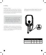
Circuit Breaker Options table

Output Amperage (A)

Circuit Breaker Options (A)

16A

20A

32A

40A

40A

50A

48A

60A

WARNING

This manual contains important instructions for the Sparkö Home 

series that shall be followed during installation, operation and 

maintenance of the unit.

WARNING

AVERTISSEMENT

Ce manuel contient des instructions importantes pour les modèles :

série EVC12 qui doit être suivie pendant l'installation, le fonctionne-

ment et la maintenance de l'unité.

1. Important Safety Instructions

Read all the instructions before using this product.

This device should be supervised when used around children.

Do not put fingers into the electric vehicle connector.

Do not use this product if the flexible power cord or EV cable is frayed, 
has broken insulation, or any other signs of damage.

Do not use this product if the enclosure or the EV connector is broken, 
cracked, open, or shows any other indication of damage.

To reduce the risk of fire, connect only to a circuit provided branch 
circuit over-current protection in accordance with the CSA C22.1–15 
Canadian Electrical Code, Part 1 (Canada) or NOM-001-SEDE Electrical 
installations (utility) (Mexico) or ANSI / NFPA 70 National Electrical 
Code (USA).

To avoid a risk of fire or electric shock, do not use this device with an 
extension cord.

THE SUITABILITY OF THE USE OF FLEXIBLE CORD IN ACCORDANCE 
WITH CE CODE, PART I, RULE 4-012, IS TO BE DETERMINED BY THE 
LOCAL INSPECTION AUTHORITY HAVING JURISDICTION.

Risk of electric shock. Do not remove cover or attempt to open the 
enclosure. No user serviceable parts inside. Refer servicing to qualified 
service personnel.

1

2

3

4

5

6

7

8

9

Lisez toutes les instructions avant d'utiliser ce produit.

Cet appareil doit être surveillé lorsqu'il est utilisé à proximité d'enfants.

Ne pas mettre les doigts dans le connecteur du véhicule électrique.

N'utilisez pas ce produit si le cordon d'alimentation flexible ou le câble EV 
est effiloché, a une isolation cassée, ou tout autre signe de dommage.

N'utilisez pas ce produit si le boîtier ou le connecteur EV est cassé, 
fissuré, ouvert ou montre toute autre indication de dommage.

Pour réduire les risques d'incendie, ne connecter qu'à un circuit 
protection contre les surintensités des circuits de dérivation conformé-
ment à la norme canadienne CSA C22.1-15 Code électrique, partie 1 
(Canada) ou NOM-001-SEDE Installations électriques (service public)
(Mexique) ou ANSI / NFPA 70 National Electrical Code (États-Unis).

Pour éviter tout risque d'incendie ou de choc électrique, n'utilisez pas 
cet appareil avec une rallonge.

L'ADÉQUATION DE L'UTILISATION DU CORDON FLEXIBLE SELON LE 
CODE CE,LA PARTIE I, RÈGLE 4-012, DOIT ÊTRE DÉTERMINÉE PAR 
L'AUTORITÉ LOCALE D'INSPECTION AYANT JURIDICTION.

Risque de choc électrique. Ne retirez pas le couvercle et n'essayez pas 
d'ouvrir le boîtier. Aucun utilisateur pièces réparables à l'intérieur. 
Confiez l'entretien à un personnel d'entretien qualifié.

1

2

3

4

5

6

7

8

9

Circuit Breaker Options table

Output Amperage (A)

Circuit Breaker Options (A)

16A

20A

32A

40A

40A

50A

48A

60A

Содержание Home

Страница 1: ...HOME U S E R M A N U A L Fast Level 2 Eletric Vehicle Charger ...

Страница 2: ...THANK YOU for accelerating Earth s transition to sustainable energy ...

Страница 3: ...INSPECTION AUTHORITY HAVING JURISDICTION Risk of electric shock Do not remove cover or attempt to open the enclosure No user serviceable parts inside Refer servicing to qualified service personnel 1 2 3 4 5 6 7 8 9 Lisez toutes les instructions avant d utiliser ce produit Cet appareil doit être surveillé lorsqu il est utilisé à proximité d enfants Ne pas mettre les doigts dans le connecteur du véh...

Страница 4: ...les These limits are designed to provide reasonable protec tion against harmful interference when the equipment is operated in a commercial environment This equipment generates uses and can radiate radio frequency energy and if not installed and used in accordance with the instruction manual may cause harmful interference to radio communica tions Operation of this equipment in a residential area i...

Страница 5: ...Supply Circuits Particular Requirements for Protection Devices for Use in Charging Systems UL 2251 Plugs Receptacles and Couplers for Electric Vehicles UL 62 Flexible Cords and Cables UL 991 Tests for Safety Related Controls Employing Solid State Devices UL 1998 Software in Programmable Componets NFPA 70 Article 625 National Electrical Code Electric Vehicle Charging System UL 840 Clearance and Cre...

Страница 6: ... 16 32 40 48A 60 Hz UVP OVP RCD SPD Ground Fault Protection OCP OTP Control Pilot Fault Protection SAE J1772 AC Charging Connector 40 F to 158 F 22 F to 122 F 95 RH Maximum 95 RH Maximum LAN Version Wi Fi Bluetooth Version 10M 100M Base T 802 11 b g n 18ft Type 3 Wall Mounted Red Green Blue LED 07 08 5 Status Description of the Charger Indication Light Standby Blue Light The READY light stays stea...

Страница 7: ... to preview the user manual and ensure local building and electrical codes are reviewed before installing the AC charger The AC charger should be installed by a qualified technician according to the user manual and local safety regulations Use appropriate protection when connecting to the main power distribution cable Type B C or D breaker with the rating current for table should be installed in t...

Страница 8: ...ique Vérifiez auprès d un électricien ou d un technicien qualifié si vous n êtes pas sûr que le produit soit correctement mis à la terre Ne modifiez pas la fiche fournie avec le produit si elle ne rentre pas dans la prise faites installer une prise appropriée par un électricien qualifié For safe use of electricity please add circuit breaker protection in the input part of charging pile Connect the...

Страница 9: ...le XLPE or equivalent cable to pull the cable from the distribution box Level ruler Pencil or marker Machine drill Step 1 Set the positions of the 4 screw holes and drill them with a diameter of 8mm and a depth of 52mm Use 4 sets expansion screw and M6 screw to fix the wall mounted bracket on the wall Step 2 Align the rear notch of charger into the wall mounted bracket and fit the screw holes of t...

Страница 10: ...orization Connect to Vehicle Charging Inlet Charging Message Charging completed 9 2 Operating Steps Step 1 Standby Mode After power on blue light READY green light CHARGE and red light FAULT all lit Enter standby mode and the blue light READY is steady on Overall outlook picture after installation Wall mounted cable winding ...

Страница 11: ...stomer Service Contact Customer Service Contact Customer Service Status Input OVP Input UVP Output OCP OTP RCD Abnormal Ground Fault Control Pilot Fault MCU Self Test Fail RCD Self Test Fail Relay Self Test Fail RCD Abnormal Stop Charging Output OCP Stop Charging OTP Stop Charging 17 18 Step 2 Plug the Charging Connector Please plug the charging connector into the vehicle charging inlet Step 3 Cha...

Страница 12: ...ree month warranty period for any subsequent paid repair work During the warranty period for any malfunction caused by normal use according to the User Manual and Service Instruction to be determined by certified maintenance technicians of Sparkö the product shall be repaired free of charge Except for the following situations the charger shall be subject to the above warranty terms 1 The warranty ...

Страница 13: ...SOP OF CONFIGURATION OF APP ...

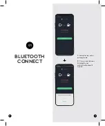
Страница 14: ...23 24 BLUETOOTH CONNECT 01 1 Add a Device enter pairing mode 2 Turn on your phone s Bluetooth and select the Bluetooth option ...

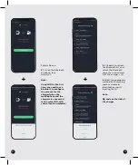
Страница 15: ...e bluetooth list and choose the bluetooth name consistent with the charger s SN 4 Select the appropriate method with scanning code or automatic identification input inputing the SN Note QR code on the side of the charger Connection complete ...

Страница 16: ...gurate wifi Add a Device Turn on Bluetooth on phone Select wifi Input SN Set your wifi account and password setting complete Restart the charger and App wating 40 seconds Add a Device Select wifi Waiting for connect complete connect complete Charging operation ...

Страница 17: ...the charger when the mobile phone and the charger are connected to the same WIFI WIFI control can be workable 3 Pull down to refresh the Bluetooth list and select the Bluetooth name that is consistent with the charger s SN 4 Select the appropriate method with scanning code or automatic identification input inputing the SN Note QR code on the side of the charger ...

Страница 18: ...t 8 Log in App again when the charger connect to the wifi Click Add a Device Note After the configuration complete you need to restart the charger waiting for about 40 seconds after restarting and try to connect 5 Input SN to the wifi configuration interface 6 Input wifi account and password to connet ...

Страница 19: ...33 9 Select wifi 10 Connection complete Note After the first configuration you only need to click the wifi to connect for everytime usage ...

Страница 20: ...HOME www thesparko com ...

Отзывы: