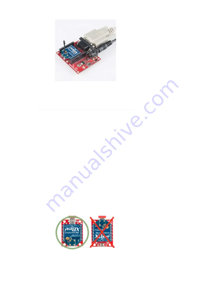
The Serial Explorer has a bigger footprint than its USB-based brethren, but
still shares most of the same features. There are RX and TX LEDs, reset
button, break-out pins, and a voltage regulator.
The Serial Explorer does require an external power supply. It’s got a barrel
jack connector which will work with either our 9V or 5V wall adapters.
If you’re using an Arduino, another option available is the XBee Shield.
That’s a subject for another tutorial.
Drivers and Assembly
The USB-based XBee Explorers all operate using an FTDI FT231X chip,
which converts serial to USB and vice-versa. This is one of our favorite
chips because it supports all computer platforms and it’s easy to work with.
If this is the first FTDI chip you’ve ever connected to your computer (it
probably won’t be your last), there is some driver installation to get out of
the way.
We’ve written a tutorial detailing How to Install FTDI Drivers tutorial. So go
ahead and
plug your USB Explorer into your computer
, and head on to
either the Windows, Mac, or Linux section there. (Ignore the final steps,
where Arduino software is invoked.)
Regardless of whether you’re on Mac or Windows, once your Explorer’s
drivers are installed it will be assigned a
unique port number
. Take note of
that port number, as you’ll need it on the next pages.
Basic Assembly: Plug In an XBee!
Time to “assemble” the XBee Explorer. Grab your XBee of choice. Notice
how it has a flat edge and a more angular/diagonal edge? Match that
footprint up to the white lines on your XBee Explorer, and carefully insert!
Take care not to bend any of the XBee pins – be gentle when you’re
plugging it in. (And be even more careful if you’re removing it!)
Page 4 of 16


