background image

Southworth Products

PUN Manual

PUN Manual

11

The power unit is designed for three-phase AC. If you connect 

the power so the motor runs backwards, the bucket will not 

move, and you may damage the pump. Do not operate the unit for 

more than 2 or 3 seconds if you think the motor might be turning 

backwards.

4.5  Checking the Hydraulic System

Check the level of the hydraulic fluid in the system. With the bucket lowered completely, 

the hydraulic fluid can be checked by viewing the sight gauge on the reservoir of the power 

unit.

4.6  Testing

1.  Clear the area around the unit.  Remove any materials which might get in the 

way of the bucket as it raises or lowers. Be sure that the safety guards are in 

place on both sides of the unit.

2.  Warn others to stay away from the unit. Operate the unit through its full range 

of travel. The bucket should rise smoothly with a quiet humming sound, and 

lower smoothly and quietly. Raise and lower the bucket a few times to check the 

operation.

3. 

As the bucket lowers, notice how the bottom of the enclosure meets the floor. 

The front edge (load edge) of the enclosure should touch at the same time 

as any other part of the enclosure. If any other part of the base of the bucket 

touches before the front edge, the floor is not flat. Insert shims above the low 

spots on the floor, so that the base is flat and level.

If another part of the bucket touches the floor before the front 

edge, the machine may not stop automatically at the correct 

moment. This may cause the machine to try to lift itself off of the 

floor.

If the “Tilt Down” proximity switch is out of adjustment, the 

machine may continue to run when it should be stopped. This 

may cause the machine to try to lift itself off of the floor. This 

could cause damage to the unit.

4. 

As a final step, clean up all spilled hydraulic fluid. Spilled hydraulic oil is slippery, 

and may present a fire hazard. If you clean up any spilled fluid, you will be able 

to tell right away if the unit begins to leak.
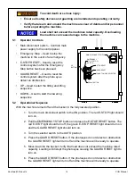
5. 

Operation

To avoid death or serious injury:

• 

Only trained and/or qualified personnel may operate the machine.

•  Crush, pinch, and shear points exist; keep hands, feet, and loose clothing 

away from moving parts. 

Содержание Pallet Unloader

Страница 1: ...UN Installation Operation Maintenance Manual Southworth Products Corp P O Box 1380 Portland ME 04104 1380 Phone 207 878 0700 or 800 743 1000 Fax 207 797 4734 www SouthworthProducts com Email Service S...

Страница 2: ...n 8 4 1 Preparation 8 4 2 Positioning the Machine 9 4 3 Hydraulic Connections 9 4 4 Electrical Connections 10 4 5 Checking the Hydraulic System 11 4 6 Testing 11 5 Operation 11 5 1 Operator Controls 1...

Страница 3: ...3 Setting End of Travel for Tilt Down Function 20 8 4 Inspecting and Cleaning the Control Valve 20 8 5 Repacking a Cylinder 22 8 6 Replacing a Cylinder 23 9 Hydraulic System Information 25 9 1 Hydraul...

Страница 4: ...on manual is not intended to be or to create any other warranty express or implied including any implied warranty of merchantability or fitness for a particular purpose all of which are hereby express...

Страница 5: ...ade only with written permission from Southworth 2 Safety Before installing operating or servicing this machine read understand and follow all safety instructions and warnings 2 1 Safety Alert Symbols...

Страница 6: ...res to protect the operator and nearby personnel from severe injury or death These features and devices shall be installed and functioning correctly during operation Side Guarding Protects operator an...

Страница 7: ...Southworth Products PUN Manual 7 3 2 Label Locations 3 4 APPLY 2995191T TO BOTTOM OF ENCLOSURE SHOULD BE CENTERED AND WHEN ENCLOSURE IS TILTED 90 1 2...

Страница 8: ...e sure to read and understand all of the warnings Select the location where the unit will be installed Choose a location where the floor is firm flat and level As the unit operates it is very importan...

Страница 9: ...material and unskid the unit Move the unit into position supporting the base of the unit 2 Level the machine using shims as necessary Grout beneath the entire base from leave no gaps Allow grout to fu...

Страница 10: ...s 3 Connect port C to the base of the lifting cylinders 4 Connect Vent Line from top of lifting cylinders to the tank 4 4 Electrical Connections To avoid death or serious injury This unit requires thr...

Страница 11: ...rs notice how the bottom of the enclosure meets the floor The front edge load edge of the enclosure should touch at the same time as any other part of the enclosure If any other part of the base of th...

Страница 12: ...onal Sequence With the machine turned off and the bucket in the fully lowered position 1 Turn the main disconnect switch to the ON position The red E STOP light should turn on 2 Pull the EMERGENCY STO...

Страница 13: ...ntil the obstruction is cleared and the GUARD RESET button has been pressed If the EMERGENCY STOP button has been pressed Steps 2 3 must be performed to resume operation 5 3 Run Time Fault Sequence If...

Страница 14: ...UN Manual 14 2 To test and diagnose problems with the machine by using the UP and DOWN buttons 5 5 Operational Sequence Illustration FULLY LOWERED POSITION TILTED TO TILT UP PROXIMITY SWITCH FULL TILT...

Страница 15: ...be removed safely from either the tilt or dump mechanisms when the bucket is completely lowered Normally you should never need to work under the bucket Always stay clear of the space under this enclo...

Страница 16: ...the tilt frame on to the support stands This may damage the machine and over stress the floor anchors 7 Turn the main disconnect switch to the OFF position Follow Lock Out Tag Out procedures 8 It is...

Страница 17: ...the main pivot pins and bushings and the cylinder clevis pins and bushings for signs of wear To avoid death or serious injury If you are going to repair the main pivot pins and bushings on either the...

Страница 18: ...er current protection in case of an overload The protective circuit will reset after it has cooled Look for anything which may be preventing the motor from turning The motor may be running backwards I...

Страница 19: ...g under any raised parts of the unit support the body of the unit using a set of strong supports The down side of the control valve for this part of the system may not be work ing The down side of the...

Страница 20: ...ing the floor Position this switch so that the bucket stops lowering when the front lip of the bucket just contacts the floor When the bucket reaches this limit the switch should send a signal to stop...

Страница 21: ...which holds the solenoid should be finger tight only 8 6 Removing a Cylinder To avoid death or serious injury All repair or maintenance shall be performed with the bucket in the fully lowered positio...

Страница 22: ...ualified hydraulic repair shop During reassembly it is very important to keep all of the parts free of dirt dust metal chips water and other contamination Most of the problems with hydraulic systems a...

Страница 23: ...diameter of the cylinder tube with a light coating of hydraulic oil Carefully insert the piston and rod back into the cylinder Be very careful not to damage the piston ring O ring or BU washer as you...

Страница 24: ...the model number and the serial number of the lift You can find these numbers on the name plate which is located on the crossbar at the base of the cylinder s When you are ordering parts for a cylind...

Страница 25: ...st and oxidation inhibitors and anti wear properties If the lift will be used at ambient temperatures below 0 F use aircraft hydraulic oil Use Type 15 aircraft hydraulic oil The following are equivale...

Страница 26: ...Southworth Products PUN Manual 26 9 2 Hydraulic Plumbing Schematic...

Страница 27: ...Southworth Products PUN Manual 27 9 3 Hydraulic Arrangement...

Страница 28: ...Southworth Products PUN Manual 28 9 4 Hydraulic Connections CONNECT PORT B TO BOTTOM CONNECTION CONNECT PORT A TO TOP CONNECTION CONNECT PORT C TO RIGHT CONNECTION...

Страница 29: ...AN AUTO MODE SELECTOR MAIN DISCONNECT SWITCH GUARD RESET E STOP RESET DOWN BUTTON EMERGENCY STOP E STOP BUTTON UP BUTTON CONTROL 2CR 1CR 6FU 4FU 5FU 1FU 4CR TRANSFORMER PLC 3FU RELAY 2FU 7FU TERMINAL...

Страница 30: ...Southworth Products PUN Manual 30 10 2 Electrical Schematic...

Страница 31: ...ch noncompliance Southworth Products Corp s obligation under this warranty is limited to the replacement or repair of defective components at its factory or another location at Southworth Products Cor...

Отзывы: