background image

South Bend Tools

For Machines Mfd. Since 12/20

Model SB1117

-41-

P A R T S

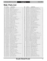
Main Parts List

REF PART #

DESCRIPTION

REF

PART #

DESCRIPTION

11

PSB1117011

HEX NUT M8-1.25

125

PSB1117125

FENDER WASHER 10 X 25 X 6

12

PSB1117012

STOP GUARD

126

PSB1117126

BUTTON HD CAP SCR M10-1.5 X 25

13

PSB1117013

BUTTON HD CAP SCR M6-1 X 8

127

PSB1117127

TENSION MOUNTING SHAFT 25 X 112

14

PSB1117014

BALL-STYLE GRAB LATCH

128

PSB1117128

SET SCREW M6-1 X 12

15

PSB1117015

FLAT HD SCR M3-.5 X 6

129

PSB1117129

SPHERICAL BEARING PB-20

16

PSB1117016

SANDING BELT 9" X 138-1/2" 180-GRIT

130

PSB1117130

FIXED HANDLE 21 X 81, M10-1.5 X 30

17

PSB1117017

FLAT WASHER 10MM

131

PSB1117131

FLAT WASHER 10MM

18

PSB1117018

LOCK WASHER 10MM

132

PSB1117132

BUTTON HD CAP SCR M10-1.5 X 16

19

PSB1117019

HEX BOLT M10-1.5 X 40

133

PSB1117133

FLAT WASHER 12MM

20

PSB1117020

PLATEN

201

PSB1117201

PILLOW BEARING UCP107

21

PSB1117021

GRAPHITE PAD BRACKET

202

PSB1117202

FLAT WASHER 12MM

22

PSB1117022

LOCK WASHER 5MM

203

PSB1117203

LOCK WASHER 12MM

23

PSB1117023

BUTTON HD CAP SCR M5-.8 X 16

204

PSB1117204

HEX BOLT M12-1.75 X 40

24

PSB1117024

GRAPHITE PAD 9" X 50-3/8"

205

PSB1117205

OSCILLATION SHAFT 35 X 355

25

PSB1117025

MACHINE BASE

206

PSB1117206

SET SCREW M10-1.5 X 10

26

PSB1117026

GUARD SUPPORT

207

PSB1117207

MOTOR MOUNT

27

PSB1117027

GEARBOX COVER

208

PSB1117208

HEX BOLT M8-1.25 X 35

28

PSB1117028

BUTTON HD CAP SCR M6-1 X 12

209

PSB1117209

LOCK WASHER 8MM

29

PSB1117029

BASE SUPPORT

210

PSB1117210

MOTOR/GEARBOX BRACKET

30

PSB1117030

FOOT M12-1.75 X 40

211

PSB1117211

BUTTON HD CAP SCR M8-1.25 X 20

31

PSB1117031

HEX BOLT M10-1.5 X 25

212

PSB1117212

FLAT WASHER 8MM

32

PSB1117032

MAG SWITCH NHD MS-18D

213

PSB1117213

CAP SCREW M12-1.75 X 35

32-1

PSB1117032-1 SWITCH BOX

214

PSB1117214

FENDER WASHER 14MM

32-2 PSB1117032-2 SWITCH BOX COVER

215

PSB1117215

DRIVE WHEEL

32-3 PSB1117032-3 CONTACTOR C-18D 220V

216

PSB1117216

MOTOR 3HP 220V 1-PH

32-4 PSB1117032-4 START BUTTON NPB22-F

216-1

PSB1117216-1

MOTOR FAN COVER

32-5 PSB1117032-5 OL RELAY NTH-17 14-17A

216-2

PSB1117216-2 MOTOR FAN

32-6 PSB1117032-6 E-STOP BUTTON TPB22-S01R

216-3

PSB1117216-3 CONTACT PLATE 24 X 67MM

33

PSB1117033

PHLP HD SCR 10-24 X 1/2

216-4

PSB1117216-4 CENTRIFUGAL SWITCH 3/4 1720 RPM

34

PSB1117034

HEX NUT M6-1

216-5

PSB1117216-5 S CAPACITOR COVER

101

PSB1117101

COMPRESSION SPRING 5.5 X 43 X 236

216-6

PSB1117216-6 S CAPACITOR 300M 250V 1-3/4 X 3-5/8

102

PSB1117102

LOCK COLLAR 49 X 60

216-7

PSB1117216-7

R CAPACITOR COVER

103

PSB1117103

ACORN NUT M12-1.75

216-8

PSB1117216-8 R CAPACITOR 20M 500V 2 X 3-5/8

104

PSB1117104

LOCK WASHER 12MM

216-9

PSB1117216-9 BALL BEARING 6308ZZ (FRONT)

105

PSB1117105

TENSION PLATE 9.5 X 31.8 X 175

216-10 PSB1117216-10 BALL BEARING 6205ZZ (REAR)

106

PSB1117106

LOCK WASHER 10MM

216-11

PSB1117216-11 MOTOR JUNCTION BOX

107

PSB1117107

CAP SCREW M10-1.5 X 20

216-12 PSB1117216-12 MOTOR CORD 12G 3W 24"

108

PSB1117108

SET SCREW M10-1.5 X 10

217

PSB1117217

FLAT WASHER 10MM

109

PSB1117109

TENSION LEVER

218

PSB1117218

LOCK WASHER 10MM

110

PSB1117110

REVOLVING HANDLE 25 X 85, M10-1.25 X 12

219

PSB1117219

HEX BOLT M10-1.5 X 35

111

PSB1117111

CAP SCREW M12-1.75 X 30

220

PSB1117220

BUTTON HD CAP SCR M8-1.25 X 25

112

PSB1117112

HEX BOLT M12-1.75 X 30

221

PSB1117221

FENDER WASHER 8MM

113

PSB1117113

BALL BEARING 6201ZZ

222

PSB1117222

GEARBOX REDUCER

114

PSB1117114

EXT RETAINING RING 25MM

223

PSB1117223

PLUG-IN SHAFT 35 X 120

115

PSB1117115

BALL BEARING 6205ZZ

224

PSB1117224

KEY 6 X 6 X 30 RE

116

PSB1117116

IDLER WHEEL

225

PSB1117225

BALL BEARING 6001ZZ

117

PSB1117117

WHEEL SHAFT 25 X 334

226

PSB1117226

HEX BOLT M10-1.5 X 30

118

PSB1117118

TENSION SHAFT 30 X 550

227

PSB1117227

SPHERICAL BEARING PB-10

119

PSB1117119

BUSHING 30 X 34 X 25

228

PSB1117228

BEARING HOUSING

120

PSB1117120

KNOB M12-1.75, 7-LOBE, D60

229

PSB1117229

ACORN NUT M10-1.25

121

PSB1117121

TAPERED THREADED ROD M12-1.75 X 155

230

PSB1117230

FLAT WASHER 8MM

122

PSB1117122

HEX NUT M12-1.75

231

PSB1117231

HEX BOLT M12-1.75 X 30

123

PSB1117123

FLAT WASHER 10MM

232

PSB1117232

GEARBOX MOUNTING BRACKET

124

PSB1117124

TENSION BRACKET

233

PSB1117233

POWER CORD 12G 3W 110" 6-20P

Содержание SB1117

Страница 1: ...A Tradition of Excellence South Bend Tools March 2021 by South Bend Tools For Machines Mfd Since 12 20 MODEL SB1117 9 X 138 OSCILLATING EDGE SANDER OWNER S MANUAL...

Страница 2: ...on is a process that happens through training and experience If you are not an experienced operator of this type of machinery read through this entire manual then learn more from an experienced operat...

Страница 3: ...ng Risks of Machinery 7 Basic Machine Safety 7 Additional Oscillating Edge Sander Safety 9 PREPARATION 10 Preparation Overview 10 Required for Setup 10 Power Supply Requirements 11 Unpacking 13 Invent...

Страница 4: ...al arrows Motor Motor Tracking Tracking Knob Knob Dust Dust Hood Hood End End Table Table End Table Height End Table Height Lock Handle Lock Handle Main Table Main Table ON Button ON Button Main Table...

Страница 5: ...ard E Belt Guard Opens and closes to allow for belt replacement and maintenance Figure Figure 2 Belt controls and components Belt controls and components Serious personal injury could occur if you con...

Страница 6: ...nts entanglement L L K K Figure Figure 5 Additional support components Additional support components Figure Figure 4 End table adjustment components End table adjustment components H End Table Tilt Lo...

Страница 7: ...urrent Rating 15A Minimum Circuit Size 20A Connection Type Cord Plug Power Cord Included Yes Power Cord Length 110 in Power Cord Gauge 12 AWG Plug Included Yes Included Plug Type 6 20 Switch Type Magn...

Страница 8: ...Width 9 1 2 in Construction Table Aluminum Frame Cast Iron Base Steel Drive Roller Rubber Idler Roller Rubber Paint Type Finish Enamel Other Related Information Number of Dust Ports 2 Dust Port Size 4...

Страница 9: ...e as follows Death or catastrophic harm WILL occur Moderate injury or fire MAY occur Death or catastrophic harm COULD occur Machine or property damage may occur Basic Machine Safety Owner s Manual All...

Страница 10: ...d by verifying that all fastening devices are properly secured and items attached to spindles have enough clearance to safely rotate Chuck Keys or Adjusting Tools Tools used to adjust spindles chucks...

Страница 11: ...avoid these hazards DO NOT wear loose clothing gloves or jewelry and tie back long hair Keep all guards in place and secure In Running Nip Points The gap between moving sandpaper and fixed table supp...

Страница 12: ...Hardware As Needed Calipers or Measuring Tape Wrench or Socket 17mm Dust Collection System Dust Hose 4 Hose Clamp 4 Open End Wrench 19mm The purpose of the preparation section is to help you prepare...

Страница 13: ...reduce the risk of these hazards avoid overloading the machine during operation and make sure it is connected to a power supply circuit that meets the requirements in the following section Full Load...

Страница 14: ...ult in a risk of electric shock The wire with green insulation with or without yellow stripes is the equipment grounding wire If repair or replacement of the power cord or plug is necessary do not con...

Страница 15: ...agent Inventory Figure Figure 8 Loose parts Loose parts NOTICE If you cannot find an item on this list carefully check around inside the machine and packaging materials Often these items get lost in...

Страница 16: ...Put on safety glasses and disposable gloves 2 Coat all surfaces that have rust preventative with a liberal amount of your cleaner or degreaser and let them soak for a few minutes 3 Wipe off the surfac...

Страница 17: ...d by the maintenance and service described in this manual Physical Environment The physical environment where your machine is operated is important for safe operation and longevity of parts For best r...

Страница 18: ...Machine mounts offer certain advantages such as ease of installation vibration dampening and easy leveling They also make it easier to relocate the machine later on The disadvantage of machine mounts...

Страница 19: ...rd and back stop door Assembly of the Model SB1117 consists of installing the sanding belt and end table 4 Move belt tension lever up and toward contour drum as shown in Figure 16 Figure Figure 16 Mov...

Страница 20: ...d lock knob installed Belt guard lock knob installed Knob Bolt Knob Bolt 1 of 2 1 of 2 x 2 8 Loosen main table tilt lock handles see Figure 20 Figure Figure 20 Location of main table tilt lock handles...

Страница 21: ...than 1 16 proceed to Step 12 Figure Figure 21 Main table tilt scale and pointer Main table tilt scale and pointer Tilt Scale Tilt Scale Pointer Pointer Lock Bolts Lock Bolts 12 Loosen lock bolts show...

Страница 22: ...y Dust Collection This machine creates a lot of wood chips dust during operation Breathing airborne dust on a regular basis can result in permanent respiratory illness Reduce your risk by wearing a re...

Страница 23: ...etting E Stop button try to start machine by pressing ON button Machine should not start If machine does not start safety feature of E Stop button is working correctly Congratulations Test run is comp...

Страница 24: ...view is to provide the novice machine operator with a basic understanding of how the machine is used during operation so they can more easily understand the controls discussed later in this manual Not...

Страница 25: ...on the sanding belt increases the risk of kickback and yields poor results Sanding Tips Avoid sanding a workpiece more than is necessary since doing so will unnecessarily decrease belt life and cost y...

Страница 26: ...ACHINE FROM POWER 2 Remove 2 belt guard lock knobs and washers see Figure 28 3 Loosen back stop lock knob see Figure 28 and open belt guard and back stop door Figure Figure 28 Belt guard components Be...

Страница 27: ...e belt tension lever down to tension sanding belt see Figure 32 8 Close belt guard and secure with lock knobs and washers removed in Step 2 9 Belt MUST be pre tracked before connecting machine to powe...

Страница 28: ...gures 33 34 Note Adjust tracking adjustment knob in about 1 turn increments Even Spaces Even Spaces on Both Sides on Both Sides Figure Figure 34 Example of sanding belt centered on drive Example of sa...

Страница 29: ...d run just long enough to observe belt tracking across drums and platen If belt tracks centered on drums no adjustment is necessary If belt does not track centered on drums proceed to Step 4 4 DISCONN...

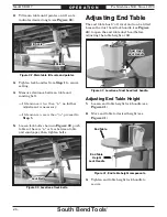
Страница 30: ...ble dust hood before adjusting the table height or tilt Adjusting End Table Height 1 Loosen end table height lock handle see Figure 41 2 Move end table to desired height see Figure 41 3 Tighten end ta...

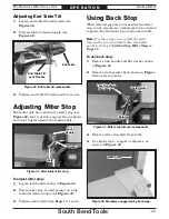
Страница 31: ...4 2 Remove scale pointer knob shown in Figure 44 to remove pointer Scale Pointer Scale Pointer Knob Knob Pointer Pointer Figure Figure 44 Miter stop removal components Miter stop removal components Lo...

Страница 32: ...2 Raise main table to desired height and adjust table tilt to desired setting refer to Adjusting Main Table on Page 27 3 Support workpiece against miter stop and slowly feed workpiece into moving belt...

Страница 33: ...g belt with light even pressure see Figures 50 51 DO NOT force workpiece against belt To contour sand 1 Open end table dust hood 2 Raise end table to desired height and adjust table tilt to desired se...

Страница 34: ...ecommended accessories A O Sanding Belts 9 x 138 H4181 60 Grit H4182 80 Grit H4183 100 Grit H4184 120 Grit H4185 150 Grit These belts feature tough aluminum oxide grain and are sized for the Model SB1...

Страница 35: ...resin dissolving cleaner to remove it Protect the unpainted cast iron table by wiping it clean after every use this ensures moisture from wood dust does not remain on bare metal surfaces Keep the tab...

Страница 36: ...ch 3mm 1 Figure Figure 57 Square positioned to check table angle Square positioned to check table angle Platen Platen Main Table Main Table 90 90 Square Square 4 Adjust main table angle until perpendi...

Страница 37: ...er angle Square positioned to miter angle Platen Platen Miter Stop Miter Stop 90 90 Square Square 4 Adjust miter stop angle until perpendicular to face of platen If miter scale reads 0 when miter stop...

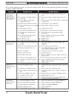
Страница 38: ...adjusted properly 2 Adjust stand feet to stabilize machine 3 Drive wheel cap screw is missing or loose 3 Inspect keys and set screws Replace or tighten if necessary 4 Motor fan rubbing on fan cover 4...

Страница 39: ...esign dust collection system Burn marks on workpiece 1 Using too fine of sanding grit 1 Use coarser grit sanding belt Page 24 2 Too much pressure against belt 2 Reduce pressure on workpiece while sand...

Страница 40: ...ble results including serious injury or fire Motor Wiring The motor wiring shown in these diagrams is current at the time of printing but it may not match your machine Always use the wiring diagram in...

Страница 41: ...d 2T1 6T3 14NO 4T2 1L1 5L3 13NO 3L2 NHD C 18D 220V 2T1 4T2 6T3 A2 O R 1 6 17 14 NHD NTH 17 1 5 98 97 96 95 U W L3 L3 L1 L1 Motor 220V 300MFD 250VAC Start Capacitor 20uF 500VAC Run Capacitor U W Ground...

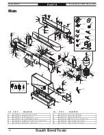
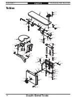
Страница 42: ...29 125 106 126 124 130 128 118 119 117 106 131 132 122 104 110 109 133 103 107 106 101 111 112 104 113 104 103 102 108 105 216 1 216 2 216 3 216 4 216 9 216 10 216 11 216 8 216 7 216 6 216 5 233 216 1...

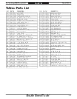
Страница 43: ...216 1 MOTOR FAN COVER 32 5 PSB1117032 5 OL RELAY NTH 17 14 17A 216 2 PSB1117216 2 MOTOR FAN 32 6 PSB1117032 6 E STOP BUTTON TPB22 S01R 216 3 PSB1117216 3 CONTACT PLATE 24 X 67MM 33 PSB1117033 PHLP HD...

Страница 44: ...310 311 312 322 314 315 316 311 317 316 311 321 320 319 318 323 316 311 324 325 326 327 328 335 327 326 339 333 338 341 333 336 337 313 342 329 340 330 331 332 331 348 347 345 344 343 346 334 329 348...

Страница 45: ...SB1117352 SET SCREW M8 1 25 X 12 317 PSB1117317 FIXED HANDLE 21 X 81 M10 1 5 X 35 353 PSB1117353 BUTTON HD CAP SCR M5 8 X 6 318 PSB1117318 BUTTON HD CAP SCR M5 8 X 10 354 PSB1117354 DUST COVER PLATE 3...

Страница 46: ...y children or untrained users restrict access or disable machine when unattended SINCE 1906 The safety labels provided with your machine are used to make the operator aware of the machine hazards and...

Страница 47: ...standard of any domestic or foreign government industry or authority In no event shall South Bend s liability under this warranty exceed the original purchase price paid for this machine Any legal act...

Страница 48: ...southbendtools com Printed In Taiwan CS21567...

Отзывы: