ESTABLISHING POLARITY
It is very important that left and right connections be made with the same plus minus polarity.
l
Most speaker wire is polarity coded. This means that each conductor is labeled either ( + ) or The positive ( + )
conductor may be a different color or texture than the negative ( ) conductor. For instance, it may be copper-colored
(instead of silver colored), have a series of fine ridges stamped in it or simply be labeled with little ( ) marks.
l
Most speaker and subwoofer terminals are color coded: Red for positive ( + ) and black for negative
l
Any connection that uses speaker wire requires care in maintaining polarity. When connecting speakers or a subwoofer to
speaker terminals, make sure to connect ( + ) wires to ( + ) terminals, and ( ) wires to ( ) terminals. For example, if
your speaker wire has one copper-colored conductor and one silvered-colored connector, connect both ends of the copper-
colored
wire ( + ) to red ( + ) terminals. Likewise, connect the wire you have identified as negative ( in this case, the
silver colored wire to black terminals.
SPEAKER WIRE TYPE
The choice of speaker
type is dependent on the type of amplifier, the distance you intend to run the wire and your budget.
In
general, you should not use extremely thin wire. If in doubt as to what brand or type of wire to use, consult your audio dealer.
LENGTH OF SPEAKER WIRES
When hooking-up your main satellite speakers, make the hook-up wires the SAME LENGTH for BOTH speakers, even if one
is much closer to your amplifier than the other one. You may need to loosely coil up part of one channel’s wire behind the ampli-
fier if one speaker is quite close and the other far away from the amplifier or receiver. But it’s worth it. Keeping both wires the
same length will help maintain proper signal balance and imaging. Likewise, when making connections between your receiver
and the
FROM SPEAKERS terminals, make the wire lengths the same.
whether the receiver has line level outputs (most don’t). Look on the
back of the unit or consult the owners manual. Line level outputs are often part of a set of
four jacks connected by small shaped connectors and marked
and
“MAIN
These outputs are also sometimes marked
OUT
outputs with
connectors.
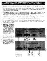
Method A.- AMPLIFIER WIRING HOOK-UP
two Instances where
Method A Amplifier
would be used,
Method A-l
Hook-Up for Most Receivers (as shown in the drawing on page 5) should be used if the
receiver or integrated amplifier does NOT have line level outputs.
Method A-2
Wiring Hook-Up Steps for A/V Surround Sound Receivers should be used if the receiver does not
have line level outputs, but has a
Out connector. Proceed to page 6.
ethod B
l
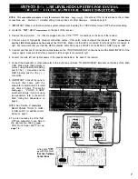
- LINE LEVEL HOOK-UP
Method
receiver or
line
outputs. Some of the “deluxe” receivers and
integrated amplifiers also have separate line level outputs. See page
7.
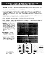
Method
power
All preamplifiers have left and right line level outputs which are con-
trolled by the preamp’s volume control. These are marked;
or MAIN OUT. See page 8.
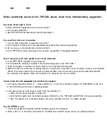
Method B-3 A/V Surround Sound Receiver or outboard decoder. Most multi-channel
Surround Sound
Receivers and separate decoders have a dedicated line level output for subwoofer operation. This output, usually labeled
Subwoofer Out can be directly connected to the LEFT or RIGHT Line connections on the THP-CXB. For
increased performance, use an RCA
adapter single female dual male to apply the
Out to both
LEFT and RIGHT Line
on the THP-CXB . See page 9.
NOTE: Some surround
processors
have their own internal crossovers assigned to the
OUTPUT connection. Consult the
Surround Sound Processors owner’s manual to determine if the unit has an internal crossover. Combining the THP-CXB crossover with the
crossover in the surround sound processor may result in low output
and’ increased noise. If this condition arises, use; Method A-l
Amplifier
For
Receivers
the
main speaker terminal outputs of the
receiver or processor.
TWO SUBWOOFERS If using two
subwoofers wired together in parallel, set the
switch on the back of the
to the
position. Do not attempt to use TWO subwoofers that create less than a combined 4 ohms load to the THP-CXB.

