


EVCS_Remote Node_ENGND04101 1.15
1.800.338.7337 / www.soundoffsignal.com
NOTICE:
Installers and users must comply with all applicable federal, state and local laws regarding use and installation of warning devices.
Improper use or installation may void warranty coverage. To review our Limited Warranty Statement & Return Policy for this or any SoundOff Signal product, visit our website at
www.soundoffsignal.com/sales-support
. If you have questions regarding this product, contact
Technical Services
, Monday - Friday, 8 a.m. to 5 p.m. at
1.800338.7337
(press #4 to skip the
automated message). Questions or comments that do not require immediate attention may be emailed to
SUPERIOR CUSTOMER RELATIONSHIPS. SMARTLY DESIGNED LIGHTING & ELECTRONIC SOLUTIONS.
2
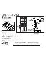
SETTING NODE ADDRESS
To set the node addresses:
1. Momentarily connect power to PIN 14.
2. Address indicator LED will wink the address (1-5).
NOTE:
•Default address is 1.
•After address 1 is set it will cycle through the addresses until it gets back to 1.
DIAGNOSTIC LED
• The diagnostic LED is steady on when the device is powered up and running with no errors.
• The diagnostic LED is off when the device is off or in sleep mode.
•The diagnostic LED winks when there is a system fault of the device is in firmware upgrade mode.
•Fault condition is read by counting the number of times the LED
“winks” on. Each fault condition will generate a pattern where each “wink” is 250ms
off/250ms on. The pattern is terminated by the LED being off for 2.5 seconds.
•The LED will wink multiple patterns when more than one fault condition is active.
FAULT CONDITION PATTERNS:
1 Wink - RPDU output(s) are faulted
2 Winks - Communication fault
3 Winks - Source voltage level is <9 VDC
4 Winks - Source voltage level is >16 VDC
5 Winks - Over temperature condition
By default even outputs flash alternating with odd outputs.
Tech Specs
nERGY Control System Remote
Node
Input Voltage:
10-16Vdc (Negative Ground)
Maximum Input Current:
50 Amps (30Amps at 85°
C)
Outputs (Sum of ALL used Outputs
Shall Not Exceed 50Amps)
4x 10Amp Solid State, Switched
6x 5Amp Solid State, Switched
IGN ON: Standby Current:
60mA
IGN OFF: Sleep Current:
0.34mA
Inputs:
4x Total
3x Active High/Low Inputs
*1x Active high/Low Input w/ System Wake up
Reverse Polarity Protection:
Not Protected (Reverse Polarity will Destroy the Devices)
Transient Protection:
Protected
High Voltage Protection:
>16V; High Voltage Error Code Set
Low Voltage Protection:
<9V; Low Voltage Error Code Set
Operating Temp:
-40
˚
C to + 65
˚
C (85
°
C max current = 30Amps)
Dimensions:
6.0” x 3.4” x .8”
Weight, Boxed:
13.2 oz.
Weight, Device Only:
10.7 oz.
Valid Input Threshold High:
>8.0V
Valid Input Threshold Low:
<1.5V
Hermetically sealed providing protection in wet areas.
•Install fuse or breaker (50Amps max.) on main power supply.
•Do NOT connect product to strobe power supply. Product is self-contained; no external power supply
needed.
•Follow attached Wiring and Interconnect requirements.
•
Torque the provided M8 nuts with lock washer to a maximum of 7ft-lbs.
-Verify that the lockwasher is fully seated when assembled-
WARNING
*Input 1 can be used to sense ignition status for overall system operation
Multi-color lights should be driven by outputs within the same output group
(Group 1: 1-5, Group 2: 6-10) to align timing.
By default even outputs flash alternating with odd outputs.


