EVCS_Remote Node_ENGND04101 1.15
1.800.338.7337 / www.soundoffsignal.com
NOTICE:
Installers and users must comply with all applicable federal, state and local laws regarding use and installation of warning devices.
Improper use or installation may void warranty coverage. To review our Limited Warranty Statement & Return Policy for this or any SoundOff Signal product, visit our website at
www.soundoffsignal.com/sales-support
. If you have questions regarding this product, contact
Technical Services
, Monday - Friday, 8 a.m. to 5 p.m. at
1.800338.7337
(press #4 to skip the
automated message). Questions or comments that do not require immediate attention may be emailed to
SUPERIOR CUSTOMER RELATIONSHIPS. SMARTLY DESIGNED LIGHTING & ELECTRONIC SOLUTIONS.
1
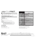
Please see next page for
Technical Specifications
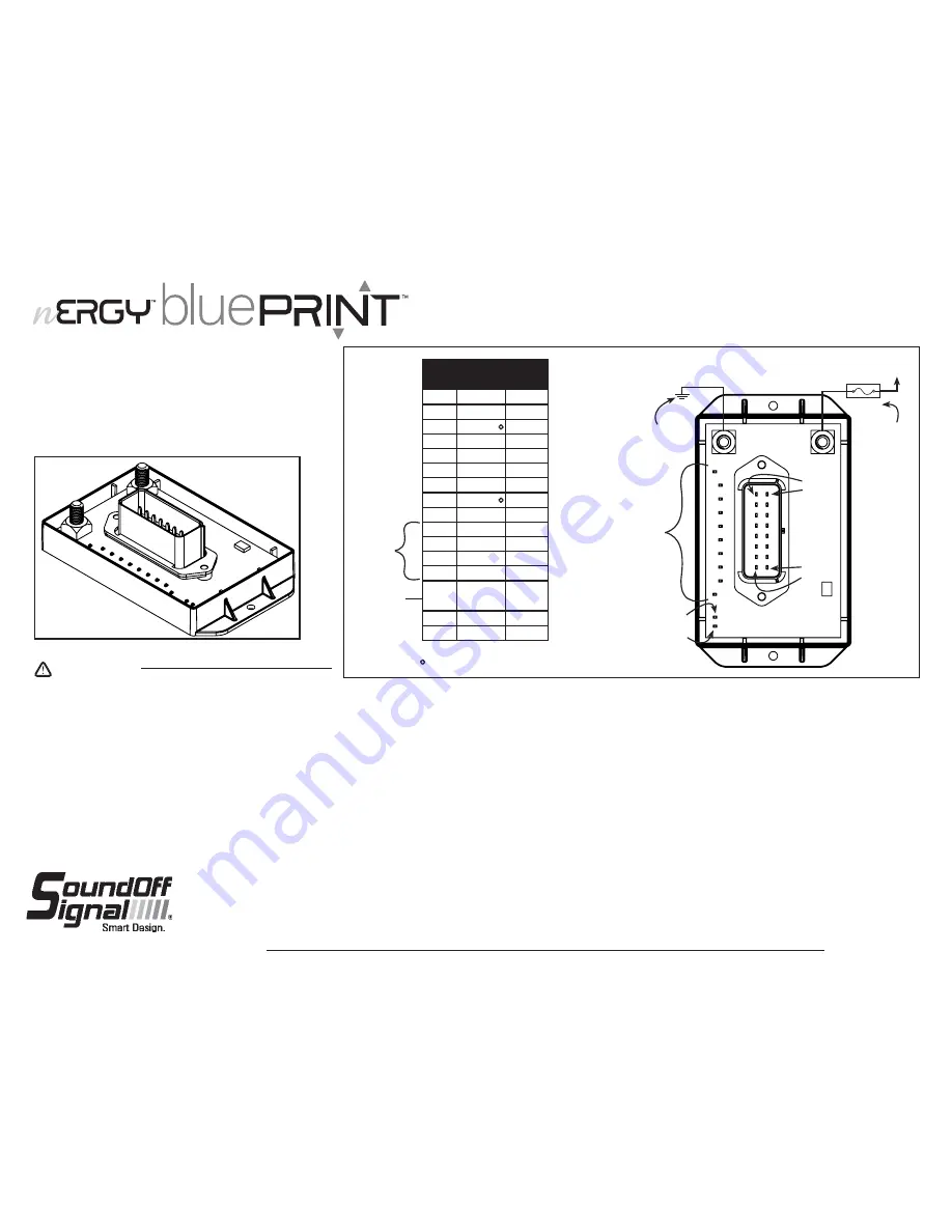
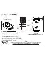
REMOTE NODE
PART NUMBER: ENGND04101
The Remote Node provides 10 outputs for connection to
vehicle devices (50 Amps max).
•(4) 10-amp solid state switchable outputs
•(6) 5-amp solid state switchable outputs.
The Remote Node also provides 4 inputs to control systems.
•Active High/Low selectable.
See attached Install Template to aid in connections and programming
+
(Power)
-
(Ground)
Wire
Pin #
Wire
Function
Amp
1
OUTPUT 9
10 Amp
2
OUTPUT 8
5 Amp
3
OUTPUT 7
10 Amp
4
OUTPUT 6
5 Amp
5
OUTPUT 5
5 Amp
6
OUTPUT 4
10 Amp
7
OUTPUT 3
5 Amp
8
OUTPUT 2
10 Amp
9
OUTPUT 10
5 Amp
10
INPUT 1
*
11
INPUT 2
12
INPUT 3
13
INPUT 4
14
ADDRESS
SELECT
15
DATA
16
OUTPUT 1
5 Amp
PIN 1
PIN 8
PIN 16
PIN 9
OUTPUT INDICATOR LED’S
FOR OUTPUTS 1-10
10
1
ADDRESS INDICATOR LED
DIAGNOSTIC INDICATOR LED
ACTIVE LOW
OR HIGH
MOMENTARY
ACTIVE HIGH
AUTOMOTIVE 50
AMP MAX FUSE
OR BREAKER
*Input 1 can be used as general purpose input
or as a system ignition input.
Higher inrush current threshold - Xenon
V
BATT
DIRECT BATT GROUND
CONNECTION
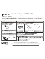
•HIGH CURRENT interconnects must be properly terminated. Poor crimp quality can cause heat
build-up and fire. Follow crimp connector manufacturer instructions.
•DO NOT install this product or route any wires in the Air Bag Deployment Zone. Refer to vehicle
Owner’s Manual for deployment zones.
•Do NOT use system to disconnect headlights, brake lights or other safety equipment.
•Unit may become hot to touch during normal operation.
•Failure to properly install connectors, fuses or wiring may cause vehicle failure or fire.
•Installation must only be performed by trained technician. Installer must determine vehicle wiring
configuration and proper integration of system.
•Use proper wire gauge. All power wires connecting to positive (+) or negative (-) battery terminal
or local chassis ground (-) must be sized to supply at least 125% of max. current and properly fused at
power source.
•Install protective grommets when routing wire through firewall or metal.
WARNING


