EVCS_Control Panel_ENGCP18001 5.16
1.800.338.7337 / www.soundoffsignal.com
NOTICE:
Installers and users must comply with all applicable federal, state and local laws regarding use and installation of warning devices.
Improper use or installation may void warranty coverage. To review our Limited Warranty Statement & Return Policy for this or any SoundOff Signal product, visit our website at
www.soundoffsignal.com/sales-support
. If you have questions regarding this product, contact
Technical Services
, Monday - Friday, 8 a.m. to 5 p.m. at
1.800338.7337
(press #4 to skip the
automated message). Questions or comments that do not require immediate attention may be emailed to
SUPERIOR CUSTOMER RELATIONSHIPS. SMARTLY DESIGNED LIGHTING & ELECTRONIC SOLUTIONS.
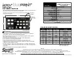
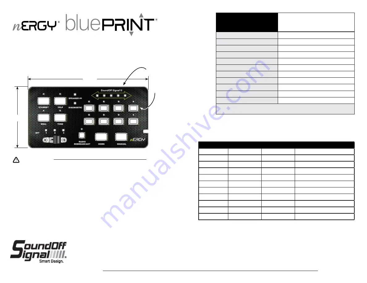
6.9”W
3.5”H
Arrow Indication
ON (Red) when
function is active
*Buttons are Backlit
CONTROL PANEL
PART NUMBER: ENGCP18001
The Control Panel features 8 (eight) auxiliary buttons for one-touch programming and a three-position slide switch to
allow convenient switching for the most frequently used warning modes.
It also features an eight-second buzzer alert to notify users that the level or auxiliary buttons are activated and
dimmable green LED backlighting.
.
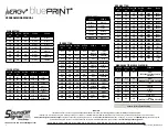
Tech Specs
nERGY Control System
Control Panel
Input Voltage:
10-16Vdc (Negative Ground)
Sleep Current:
8 mA
Inputs:
1x 3pin MIC Input
Reverse Polarity Protection:
Protected
Transient Protection:
Protected
High Voltage Protection:
Protected
Low Voltage Protection:
Protected
Operating Temp:
-40
˚
C to + 65
˚
C
Dimensions:
6.9”H x 3.5”Wx 1.2”D
Weight, Boxed:
1.3lb.
Weight, Device Only:
1.1lb
The control panel is not waterproof. Install in a protected location away from excessive
heat and moisture.
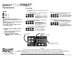
* SIREN AUDIO BUTTON ACTIVATED
(EXCEPT RADIO REBROADCAST)
STANDBY
SPKR 1 INDICATOR
SPKR 2 INDICATOR
CONDITION
FLASHING
ON
ON
OVER-TEMPERATURE, (380R ONLY)
FLASHING
OFF
ON
UNDER-VOLTAGE
FLASHING
ON
OFF
OVER-VOLTAGE
FLASHING
FLASHING
-
COMM FAULT - RELAY
FLASHING
-
FLASHING
COMM FAULT - AMP
FLASHING
FLASHING
FLASHING
COMM FAULT -CENTRAL CONTROLLER
ON
-
-
STANDBY MODE
*OFF
ON
-
SPKR 1 IS ACTIVE
*OFF
-
ON
SPKR 2 IS ACTIVE
*OFF
OFF
-
SPKR 1 IS NON-FUNCTIONING
*OFF
-
OFF
SPKR 2 IS NON-FUNCTIONING
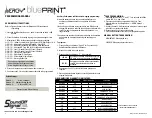
SIREN AMPLIFIER DIAGNOSTIC INDICATORS:
•HIGH CURRENT interconnects must be properly terminated. Poor crimp quality can cause heat
build-up and fire. Follow crimp connector manufacturer instructions.
•DO NOT install this product or route any wires in the Air Bag Deployment Zone. Refer to vehicle
Owner’s Manual for deployment zones.
•Do NOT use system to disconnect headlights, brake lights or other safety equipment.
•Unit may become hot to touch during normal operation.
•Failure to properly install connectors, fuses or wiring may cause vehicle failure or fire.
•Installation must only be performed by trained technician. Installer must determine vehicle wiring
configuration and proper integration of system.
•Use proper wire gauge. All power wires connecting to positive (+) or negative (-) battery terminal
or local chassis ground (-) must be sized to supply at least 125% of max. current and properly fused at
power source.
•Install protective grommets when routing wire through firewall or metal.
WARNING
1

