


ETSWDAS02 -
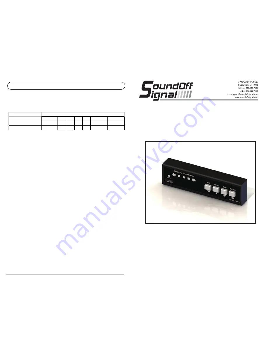
DIRECTIONAL ARROW SWITCH
INSTALLATION & OPERATION
INSTRUCTIONS
DIRECTIONAL ARROW SWITCH
PAGE 6
1
2
3
4
5
6
(Default)
7
Warning Mode One DW+EW DW EW DW EW
DW
EW
Warning Mode Two
NA
EW DW
NA
NA
DW+EW
DW+EW
Warning Mode Options
Changing between Warning output options:
Pressing the Warning button while in product configuration mode will change the outputs the warning
button controls. Below is a table of options
Directional Warning (DW) will apply voltage to the Yellow Wire (Warning One Output). End Warning
(EW) will apply voltage to the pink wire (Warning Two Output).
In modes 1,4, and 5 there is no warning mode two.
In modes 2,3,6, and 7 pressing the warning button once will activate warning mode one. Pressing the
warning button twice will activate warning mode two. To exit either warning mode, press the warning
button once.
The Current Warning Mode Option is designated by the yellow LEDs.
1.
Warning Mode setting 1 is designated by yellow LED 1.
2.
Warning Mode setting 2 is designated by yellow LED 2.
3.
Warning Mode setting 3 is designated by yellow LED 3.
4.
Warning Mode setting 4 is designated by yellow LED 4.
5.
Warning Mode setting 5 is designated by yellow LED 5.
6.
Warning Mode setting 6 is designated by yellow LED 1 and 5.
7.
Warning Mode setting 7 is designated by yellow LED 1, 2, and 5.
Note: If the warning 2 RED LED is illuminated and an arrow button is pressed, they will both be on at
the same time. Pressing the Warning button will turn of the Warning 2 output. Pressing the arrow
button that is green will turnoff the Arrow Function.
To exit product configuration mode:
By holding down the Left and Warning Buttons together for 2 seconds, product configuration mode
can be exited. The unit will emit two short beeps. At this time release the buttons.
ETSWDAS02 10.12


