Talkback
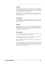
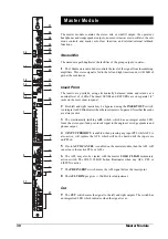
The talkback system allows communication by the operator to the group and mix
outputs, and to and from the front of house (FOH) console.
19
The
TALKBACK control adjusts the level of the talkback mic input, from a
3-pin XLR on the rear panel. The sensitivity of the mic input is variable between
-20dBu and -50dBu.
20
The
momentary
action
FOH button, which has an integral green LED, initiates
talkback to the front of house console using a Soundcraft proprietary system. The
talkback mic signal is switched to the FOH OUT XLR, with a +15v DC
common-mode voltage to signal the FOH console (a Vienna, Europa or 8000) that
talkback is occurring. The signal present on the FOH IN XLR is fed to the ’phones,
dimming the existing signal by 15dB. The wedge is dimmed by 20dB. An internal
jumper disables the common-mode DC voltage, to allow use with non-Soundcraft
desks.
If a 15v common-mode voltage is detected on the FOH IN XLR, indicating talkback
from the front-of-house console, then the FOH IN signal is switched to the ’phones
output, dimming the existing signal by 15dB, and dimming wedge output by 20dB.
The FOH switch also lights. The signal from the talkback mic. may be routed to
the group or mix outputs individually by pressing the TB button on each output;
this also dims the wedge output by 20dB.
21
The
momentary
TB switch feeds the signal from the TALKBACK MIC to the
mix outputs independently of the fader and CUT switch, dimming the output by
6db while it is active.
22
Talkback may also be routed to the mix buses by the INT talkback function
on the master module; in this case the mix CUT and fader will affect the talkback
level. The TALKBACK TO BUSES INT button, which has an integral green LED,
routes the talkback signal from the mic to all group and mix buses simultaneously,
also dimming the wedge output.
23
The TALKBACK TO BUSES EXT button , which has an integral green LED,
sends the FOH IN signal to the group and mix buses when FOH talkback is active
to allow the front-of-house engineer to talk to the performers via the monitor outputs.
Oscillator
24
The oscillator, activated by the ON switch, produces pink noise. An integral
red LED in the switch indicates when the oscillator is on.
25
The
TONE button switches the signal from pink noise to sine wave. An
integral red LED in the switch indicates when the Tone is on.
26
The TONE’s frequency is variable between 63Hz and 1kHz: it is adjusted by
the FREQ control.
27
The
X10 button, which has an integral red LED, increases the frequency up
to 630Hz and 10kHz.
28
The oscillator signal is fed to the group and stereo mix buses; the oscillator
output is also available, balanced at a nominal level of +4dBu, on an XLR on the
rear connector panel. The LEVEL control adjusts the level from off to 10dB above
nominal.
Master Module
33
Содержание SM 16
Страница 1: ...SOUNDCRAFT USER GUIDE 16 ...
Страница 5: ...Introduction Introduction 1 ...
Страница 10: ...6 Introduction ...
Страница 11: ...Installation Installation 7 ...
Страница 14: ...10 Installation ...
Страница 15: ...Module Block Diagrams Module Block Diagrams 11 ...
Страница 16: ...PFL BUS GROUPS 1 16 BUSSES R STEREO BUS L STEREO BUS Input Module 12 Module Block Diagrams ...
Страница 17: ...Group Output Module Module Block Diagrams 13 ...
Страница 18: ...Master Module 14 Module Block Diagrams ...
Страница 19: ...Input Module Input Module 15 ...
Страница 26: ...22 Input Module ...
Страница 27: ...Group Output Module Group Output Module 23 ...
Страница 32: ...28 Group Output Module ...
Страница 33: ...Master Module Master Module 29 ...
Страница 41: ...Appendices Appendices 37 ...


