*URXS2XWSXW0RGXOH
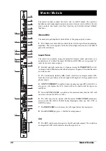
Eight output modules are fitted in each console. The output module contains two
group output sections, stacked one above the other. The lower sections control
groups 1 - 8, while the upper sections control groups 9 - 16. The two sections have
identical facilities.
Level Control
The group summing amp is assigned to one of the sixteen group buses using internal
0.1" push-on jumpers.
1
The
100mm
Fader controls the level of the signal from the summing amplifier,
which is fed to the insert send, with 10dB of gain at maximum.
Insert Point
2
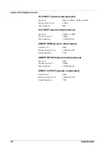
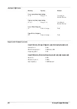
The insert point is post-fade, and uses an electronically balanced send and return
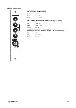
at a nominal level of +4dBu. The insert SEND and RETURN are on separate 1/4"
jacks on the rear connector panel. The insert point may be bypassed using the
INSERT OUT switch. An integral red LED indicates when the insert point is
bypassed. Note that the send is always active
Solo
3
The electronically latching AFL switch, which has an integral amber LED,
feeds the post-fade, post-insert group signal to the engineer’s wedge speakers and
phones output; however, if INPUT PRIORITY (see the Master Module) is enabled
then any active input PFLs will replace the AFL signal, and the group will not be
heard until the inputs are un-PFLed. If solo AUTO CANCEL (see the Master
Module) is selected, then the AFL will cancel any other active PFLs or AFLs. The
AFL may also be cleared with the Master Module’s SOLO CLEAR function.
4
The
PRE INSERT switch moves the AFL signal before the insert point.
5
The
AFL TRIM pot gives +/-10dB of level adjustment.
Cut
6
The
CUT switch mutes the signal to the group output and stereo mix bus (if
selected). The switch has an integral red LED which indicates when the signal is
cut.
Stereo Mix
7
The
L and R switches route the group signal to the left and right stereo mix
buses respectively. Each switch has an integral green LED. This feature allows
subgroups to be created, if the console is used in a FOH application.
3
4
10
11
12
5
9
6
7
13
2
8
1
24
Group Output Module
Содержание SM 16
Страница 1: ...SOUNDCRAFT USER GUIDE 16 ...
Страница 5: ...Introduction Introduction 1 ...
Страница 10: ...6 Introduction ...
Страница 11: ...Installation Installation 7 ...
Страница 14: ...10 Installation ...
Страница 15: ...Module Block Diagrams Module Block Diagrams 11 ...
Страница 16: ...PFL BUS GROUPS 1 16 BUSSES R STEREO BUS L STEREO BUS Input Module 12 Module Block Diagrams ...
Страница 17: ...Group Output Module Module Block Diagrams 13 ...
Страница 18: ...Master Module 14 Module Block Diagrams ...
Страница 19: ...Input Module Input Module 15 ...
Страница 26: ...22 Input Module ...
Страница 27: ...Group Output Module Group Output Module 23 ...
Страница 32: ...28 Group Output Module ...
Страница 33: ...Master Module Master Module 29 ...
Страница 41: ...Appendices Appendices 37 ...


