Read carefully before installation, commissioning and operation
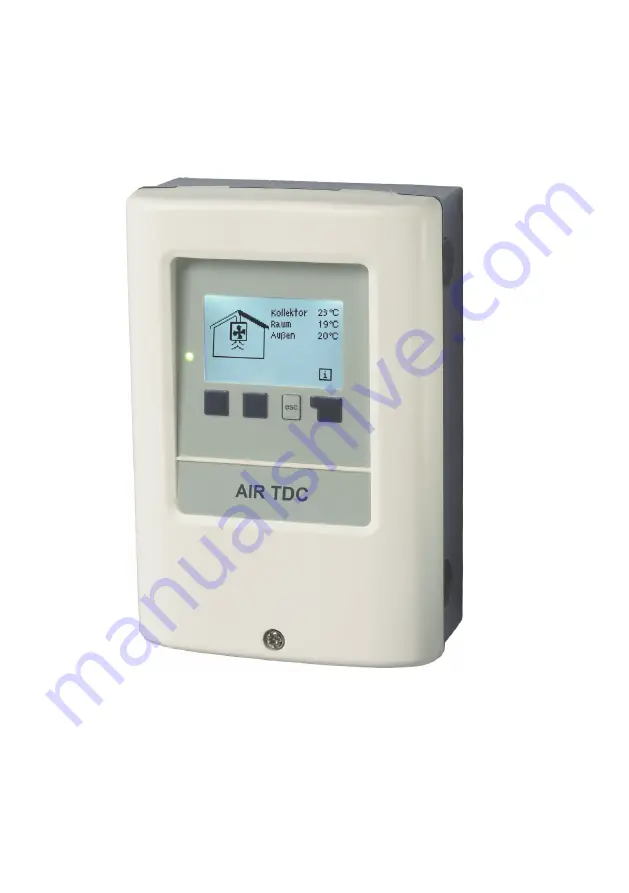
Temperature Difference Controller AIR TDC
Installation and operating instructions
Страница 1: ...Read carefully before installation commissioning and operation Temperature Difference Controller AIR TDC Installation and operating instructions...
Страница 2: ...17 3 2 Overview 17 3 3 Alternating 17 4 Operating modes 18 4 1 Automatic 18 4 2 Manual 18 4 3 Off 18 5 Settings 19 5 1 Tmin Collector 19 5 2 Tset Room 19 5 3 Collector Room 19 5 4 Tset Room 20 5 8 Co...
Страница 3: ...e applicable DIN EN standards and the installation and operating instruction of the additional system components must also be observed The controller does not under any circumstances replace any safet...
Страница 4: ...other than its intended purpose Operation above or below the limit values listed in the specifications Force majeure A 5 Warranty and liability Changes additions to or conversion of the unit are not p...
Страница 5: ...nd appliances Collector and outdoor sensor 30 m other PT1000 sensors 10 m PWM 0 10V 3 m mechanichal relay 10 m Real Time Clock RTC with 24 hour power reserve Permissible ambient conditions Ambient tem...
Страница 6: ...can be activated to prevent unintentional setting changes Resetting to factory settings A wide range of additional functions are available B 3 About the controller Description of controller Temperatur...
Страница 7: ...ot claim to be complete The controller does not replace safety devices under any circumstances Depending on the specific application additional system components and safety components may be mandatory...
Страница 8: ...ch the electronics when doing so 4 Hold the lower part of the housing up to the selected position and mark the 3 mounting holes Make sure that the wall surface is as even as possible so that the housi...
Страница 9: ...y from mains voltage cables Feed temperature sensor cables only into the left hand side of the unit and mains voltage cables only into the right hand side Caution The customer must provide an all pole...
Страница 10: ...e sensors The temperature sensor cables must be routed separately from mains voltage cables and must not for example be routed in the same cable duct The controller operates with Pt1000 temperature se...
Страница 11: ...ound output for ventilators Mains voltage 230VAC 50 60Hz Terminal Connection for R1 Ventilator N Neutral conductor N R2 Ventilator flap N Neutral conductor N L Mains phase conductor L N Mains neutral...
Страница 12: ...or is present Entries are made using four keys 3 4 which are assigned to different functions depending on the situation The esc key 3 is used to cancel an entry or to exit a menu If applicable there w...
Страница 13: ...step by step to the selection mode thus cancelling the commissioning help Finally menu 4 2 under operating mode Manual should be used to test the switch outputs with the consumers connected and to che...
Страница 14: ...ntrol of the system with oper ating hours etc Select graphics mode or overview mode Automatic mode manual mode or switch unit off Set parameters needed for normal opera tion Solar and frost protection...
Страница 15: ...y instead of the measurement value then there may be a defective or incorrect temperature sensor If the cables are too long or the sensors are not placed optimally the result may be small deviations i...
Страница 16: ...atistics 2 1 Operating Hours Display of operating hours of the ventilator connected to the controller various time ranges day year are available Display of the average temperature difference between t...
Страница 17: ...electing Exit display mode Display mode 3 Display mode 3 1 Schematic In graphics mode the selected hydraulic systems are depicted with the measured temperatures and operating states of the connected c...
Страница 18: ...thus the connected consumer are switched on and off by pressing a key with no regard to the current temperatures and the parameters which have been set The measured temperatures are also shown to pro...
Страница 19: ...ired for the control function are made in menu 5 Settings 5 1 Tmin Collector Enable start temperature at sensor 1 If this value is exceeded at the collector sensor S1 and the other conditions are also...
Страница 20: ...il TminS3 hysteresis temperature is reached Switch off temperature at sensor 3 If this value is exceeded at the applicable sensor 3 the controller switches the associ ated ventilator off If the temper...
Страница 21: ...re met the controller turns the ventilator on again 6 1 Seizing Protection 6 2 Fan Protection 6 1 1 Fan Protection 6 1 2 VS Tein Taus Caution Thisdoesnotunderanycircumstances replace the safety facili...
Страница 22: ...ed Please note that individual settings are still possible even when a profile has been selected 7 2 3 Output Signal The signal can become inverted here for special ventilating fans This function is f...
Страница 23: ...sors collector and sensor is greater than the set value then the speed is increased by one stage after the control time elapses If the temperature difference T between the reference sensors is below t...
Страница 24: ...themains voltageisinterrupted andshould bereset afterwards Deviations in the temperature values displayed for example due to cables which are to long or sensors which are not positioned optimally can...
Страница 25: ...n Keep in mind that the system is not changed adjustments made in this menu are only used to calculate the heat volume and should be based on the actual system Resulting data is only approximate value...
Страница 26: ...3 Display mode 7 4 Time date 8 Menu lock 9 Service values To lock the other menus select Menu lock on To enable the menus again select Menu lock off Setting range on off default setting off Menu lock...
Страница 27: ...for remote diagnosis by a specialist or the manu facturer in the event of an error etc The menu can be closed at any time by press ing esc Service values 9 Service values Caution Enterthevaluesatthet...
Страница 28: ...o se lect the language for the menu guidance This is queried automatically during initial commissioning The choice of languages may differ however depending on the device design Language selection is...
Страница 29: ...the warning or info symbol Possible error messages Notes for the specialist Sensor x defective Means that either the sensor the sensor input at the controller or the connecting cable is was defective...
Страница 30: ...working on the unit switch off the power supply and secure it against being switched on again Check for the absence of power Only use the supplied spare fuse or a fuse of the same design with the foll...
Страница 31: ...at the time that the suspected mal function occurs Send the service value table by fax or e mail with a brief description of the error to the specialist or manufacturer In programs 13 with pool the c...
Страница 32: ...d with the greatest possi ble care the possibility of incorrect or incomplete information cannot be excluded Subject as a basic principle to errors and technical changes Hydraulic variant set Commissi...