background image

14

XGS 5500/6500

Operating Instructions

Caution:

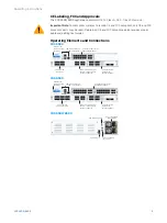
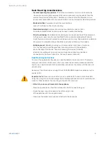
 The SFP, SFP+ and QSFP+ ports use lasers to transmit signals over fiber optic 

cable. The lasers are compliant with the requirements of a Class 1 Laser equipment and 
are inherently eye-safe in normal operation. However, you should never look directly at 
a transmit port when it is powered on. Always install appropriate and UL approved Laser 
Class I Transceivers, rated 3.3Vdc, max. 1W, in the fiber ports before using the fiber ports.

Installing a SFP/SFP+/QSFP+ module

Please read the operation manual for the module. Carefully insert the module into the port 
until it engages. The interface is immediately ready for use.

Removing a SFP/SFP+/QSFP+ module

1. 

Remove the optical cable from the module which you wish to remove.

2. 

Remove the module carefully from the port.

Depending on when you purchased your module, it may have any of three different 
release mechanisms: a plastic tab on the bottom of the module, a wire bail, or a plastic 
collar around the module.

Please read the operation manual to the module.

Serial Console

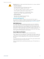
You can connect a serial console to either the RJ45 or micro USB COM port to access the 
CLI. Only one port can be used at any time. If both ports are connected then the micro USB 
port will take precedence. You can use, for instance, the Hyperterminal terminal program 
which is included with most versions of Microsoft Windows to log on to the appliance 
console. If you want to connect to the Micro-USB COM port please use the supplied cable. 
If you want to connect to the RJ45 COM port please use a RJ45 to DB9 Adapter cable (not 
provided with the unit). The Pin-out for this cable is shown in the table below.

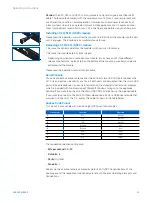
Sophos RJ45 Pinout

This pinout is compatible with Cisco Straight (X2) pinout serial cables.

Pin number

Function

Direction

1

RTS

Output

2

DTR

Output

3

TXD

Output

4

Ground

N/A

5

Ground

N/A

6

RXD

Input

7

DSR

Input

8

CTS

Input

The required connection settings are:


Ì

Bits per second:

 38,400


Ì

Data bits: 

8


Ì

Parity: 

N (none)


Ì

Stop bits:

 1

Access via the serial console is activated by default on ttyS0. The connections of the 
appliances and the respective functionality are listed in chapter ‘Operating Elements and 
Connections.’

Содержание XGS 5500

Страница 1: ...Operating Instructions XGS 5500 6500...

Страница 2: ...ls The following symbol and its meaning appears in the Hardware Quick Start Guide Safety Instructions and in these Operating Instructions Caution and Important Note If these notes are not correctly ob...

Страница 3: ...l module COM Micro USB RJ45 2 x USB 3 0 MGMT port 2 x expansion bay shown with optional modules F1 F4 F5 F8 fiber ports LAN 1 8 8 x GbE copper fixed Incl 2 bypass pairs ports 1 2 and 3 4 Multi functio...

Страница 4: ...nnect a USB 2 0 or 3 0 compatible device to this port e g USB thumb drive UPS 3G 4G dongles MGMT RJ45 10 100 1000 Mbps We recommend using this dedicated port to connect your Admin PC Module Slots Type...

Страница 5: ...C to 70 C 20 C to 70 C Operational Storage Humidity 10 to 90 non condensing 10 to 90 non condensing Operational Storage Altitude 2000 5791 m 2000 5791 m MTBF hours Telcordia SR 332 Issue 3 135099 135...

Страница 6: ...do not function correctly Speed Right LED Blue On If SFP connector is operating at 10 000 Mbps Amber On If SFP connector is operating at 1 000 Mbps Off Either the LED is not working or the SFP connec...

Страница 7: ...0 Main Menu 2 Network Menu Network Menu 1 Show Port A1 LAN Port A1 LAN 172 16 16 16 Network Menu 2 Show Port A2 WAN Port A2 WAN IP NOT ASSIGN Network Menu 3 Show Port A3 NA Port A3 NA IP NOT ASSIGN N...

Страница 8: ...ill shut down the system completely and reboot Control Key Functions The current menu is left When the key is pressed a couple of times the modifications are discarded and the initial state will be di...

Страница 9: ...key to continue 8 Factory Reset 1 Confirm Asks for Confirmation 9 ENTER Shutdown Complete Reboot Machine S NO Action Item press What you see on the LCD What it means 1 SOPHOS Protection Appliance is...

Страница 10: ...tabilizers should be attached to the rack In multiple rack installations the racks should be coupled together Always make sure the rack is stable before extending a component from the rack You should...

Страница 11: ...mes To ensure this the rack itself should be grounded Grounding screws for the appliance are on the rear of the chassis Chassis Grounding is required Particular attention should be given to power supp...

Страница 12: ...ith a RAID 1 system with two Solid State Drive A RAID system redundant array of independent disks connects several physical Solid State Drive to one particularly performing logical drive RAID 1 enhanc...

Страница 13: ...power units which are not suited for the system Exchanging a power supply unit 1 Remove the cord taking care to release the cord from the cord retention device 2 Move the green lever of the power supp...

Страница 14: ...he module Please read the operation manual to the module Serial Console You can connect a serial console to either the RJ45 or micro USB COM port to access the CLI Only one port can be used at any tim...

Страница 15: ...9409 9100 Email sales sophos com au Asia Sales Tel 65 62244168 Email salesasia sophos com Copyright 2021 Sophos Ltd All rights reserved Registered in England and Wales No 2096520 The Pentagon Abingdon...

Отзывы: