45
Camera Control Command
XCL-X700/V500
■
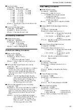
Gain-Step Setting
[Command]
GAIN-STEP
[Parameter 1] <Gain (0 to 18)> [dB]
0: 0 dB
8: 8 dB
16: 16 dB
1: 1 dB
9: 9 dB
17: 17 dB
2: 2 dB
10: 10 dB
18: 18 dB
3: 3 dB
11: 11 dB
4: 4 dB
12: 12 dB
5: 5 dB
13: 13 dB
6: 6 dB
14: 14 dB
7: 7 dB
15: 15 dB
[Process]
Sets the gain value (0 to 18 dB) in 1 dB
steps.
■
Gain-Fine Adjustment Setting
[Command]
GAIN-FINE
[Parameter 1] <Gain (0 to 1023)>
[Process]
Fine tunes the gain value.
Scan Setting Commands
■
Binning Mode Setting
[Command]
BINNING
[Parameter 1] <Mode (0 or 1)>
0: OFF
t
No binning
1: V
t
Vertical binning
[Process]
Selects a binning mode.
Partial Scan Setting Commands
■
High-rate Scan Setting
[Command]
PARTIAL
[Parameter 1] <Mode (0 or 1)>
0: OFF
1: Partial Scan (External Control)
[Process]
Selects a high-rate scan (partial scan)
mode.
■
PS2 Upper High-Speed Transfer Area Setting
[Command]
FPS
[Parameter 1] <Area (0 to 15(X700)/0 to 7(V500))>
Sets the area value so that the total sum of the
upper area value and the following lower area
value does not exceed 15 for the X700 and 7 for
the V500.
[Process]
Sets the Upper High-Speed Transfer
Areas while performing the Partial Scan
II. For details, refer to “Settings for
High-rate scan II.” See page 21 for the
X700 and page 38 for the V500.
■
PS2 Lower High-Speed Transfer Area Setting
[Command]
RPS
[Parameter 1] <Area (0 to 15(X700)/0 to 7(V500))>
Sets the area value so that the total sum of the
upper area value above and the lower area value
does not exceed 15 for the X700 and 7 for the
V500.
[Process]
Sets the Lower High-Speed Transfer
Areas while performing the Partial Scan
II. For details, refer to “Settings for
High-rate scan II.” See page 21 for the
X700 and page 38 for the V500.
Pulse Setting Commands
■
VD/HD IN/OUT Setting
[Command]
VHINTEXT
[Parameter 1] <IN/OUT (0 or 1)>
0: VD/HD external (Inputs external
synchronous signals)
1: VD/HD internal (Outputs internal
synchronous signals)
[Process]
Sets either input or output for VD/HD
signals.
■
External HD/VD/CLK Signal Input Selection
Setting
[Command]
EXTHVCLK
[Parameter 1] <Input selection (0 or 1)>
0: Camera Link
t
Through the Camera Link
connector
1: DC-700/CE
t
Through the 12 pin DC
connector
[Process]
Specifies an input path for External HD/
VD/CLK signals.
■
External Trigger Signal Input Selection
[Command]
EXTTRG
[Parameter 1] <Input selection (0 or 1)>
0: Camera Link
t
Through the Camera Link
connector
1: DC-700/CE
t
Through the 12 pin DC
connector
[Process]
Specifies an input path for external
trigger signals.
■
Overlap Setting
[Command]
TRG-OVLP
[Parameter 1] <Overlap selection (0 or 1)>
0: OFF
1: ON
[Process]
Enables or disenables the Overlap
function.
■
75 ohm Termination Setting
[Command]
TERM
[Parameter 1] <Termination (0 or 1)>
0: ON
1: OFF
[Process]
Sets 75 ohm termination ON/OFF.
■
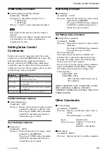
Master Clock Select Setting
[Command]
CLKSEL
[Parameter 1] < CLK (0 or 1)>
0: MASTCK
t
Internal Clock
1: EXT_MASTCK
t
External Clock
[Process] Selects an internal or external master
clock.


