background image

Before adjustment

59 

(GB)

Before adjustment

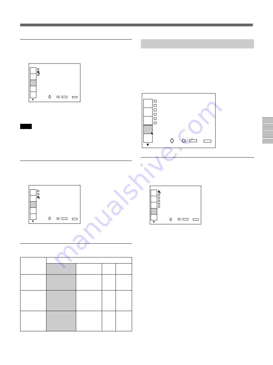
DRC (Digital Reality Creation)

Set to ON to make the NTSC signal 4-times density
image.

                                      V I D E O 
          C O M B   F I L T E R : 3 D 
          D R C : O N 
          D R C   L E V E L : H I G H

PIC

CTRL

PIC

SETTING1

PIC

SETTING2

INPUT

SETTING

SEL:

SET:

ENTER

EXIT: MENU

SET

SETTING1

P

Normally set to ON.  When a 15 kHz signal is input,
the DRC function activates.  When the DRC is not
required, set to OFF.

Note

The DRC is effective only when the 15 kHz signal
complies with the timing of the video signal.  If it has a
particular timing, the image may be disturbed with the
DRC ON.

DRC LEVEL

Selects the effect of the DRC for the NTSC signal.
This item can be selected only for an interlaced signal.

                                      V I D E O 
          C O M B   F I L T E R : 3 D 
          D R C : O N 
          D R C   L E V E L : H I G H

PIC

CTRL

PIC

SETTING1

PIC

SETTING2

INPUT

SETTING

SEL:

SET:

ENTER

EXIT: MENU

SET

SETTING1

P

HIGH is preset at the factory. Select LOW if the
picture is glaring.

Input signals and adjustable/setting items

Y: Adjustable/can be set
N: Not adjustable/cannot be set

*

For the VPH-G90E model, the optional IFB-G90E Video
Interface Board is required.

The INPUT SETTING Menu

(Pro-user/Service/Expert modes)

The INPUT SETTING menu is used to adjust the input
signal.
Items that can be adjusted are displayed in green.
You cannot select the items indicated in white.

                                  I N P U T - A 
          C O L O R   T E M P : 6 5 0 0 
          C L A M P : A U T O 
          V   S H I F T : W I D E 
          S Y N C   S E L : A U T O 
          S Y N C   R O U T E : A U T O 
          V I D E O   L O C K : N O R M A L

SEL:

SET:

ENTER

EXIT: MENU

PIC

CTRL

PIC

SETTING1

PIC

SETTING2

INPUT

SETTING

SET

SETTING1

P

COLOR TEMP (Temperature)

Selects the appropriate color temperature according to
your application and the input source signal.

                                  I N P U T - A 
          C O L O R   T E M P : 6 5 0 0 
          C L A M P : A U T O 
          V   S H I F T : W I D E 
          S Y N C   S E L : A U T O 
          S Y N C   R O U T E : A U T O 
          V I D E O   L O C K : N O R M A L

SEL:

SET:

ENTER

EXIT: MENU

PIC

CTRL

PIC

SETTING1

PIC

SETTING2

INPUT

SETTING

SET

SETTING1

P

9300: standard color temperature for consumer-use

products

6500: standard color temperature for business-use

products

5400: standard color temperature for HDTV
3200: standard color temperature for medical products

and studio cameras

CUSTOM: If you wish to make the color of a

particular input signal uniform to that of another
display, select CUSTOM, then adjust the white
balance.

For details, see “Adjusting the White Balance” on page
125

 (GB)

.

Item

Input signal

COM FILTER

DRC

DRC LEVEL

Video or
S video (Y/C) 

*

Y

(NTSC

3.58

system only)

Y

Y

Component
SDI 4:2:2

N

Y

Y

HDTV

N

N

N

RGB

N

Y

(15 kHz

RGB
only)

Y

(15 kHz

RGB
only)

Содержание VPH-G90E

Страница 1: ...nual for Dealers Manuel d installation destiné aux revendeurs Manual de instalación para proveedores CAUTION THIS INSTALLATION MANUAL IS FOR USE BY QUALIFIED PERSONNEL ONLY IMPORTANT CE MANUEL D INSTALLATION EST DESTINÉ AUX PROFESSIONNELS SEULEMENT IMPORTANTE ESTE MANUAL DE INSTALACIÓN ES PARA SER USADO POR PERSONAL CUALIFICADO SOLAMENTE ...

Страница 2: ...onversion Angle 22 GB Connections Location and Function of the Rear Panel 24 GB Switching the 75 ohm Terminate Connectors VPH G90M G90U only 27 GB Connecting Directly to the Projector 29 GB Connecting Multiple Projectors 30 GB Using the PC 3000 Signal Interface Switcher 32 GB Confirming the System Construction 37 GB Using the PC 1271 1271M Signal Interface Switcher 38 GB Before Adjustment For Remo...

Страница 3: ...lug 81 GB Preparation 81 GB Adjusting the Green Lens Focus and Scheimpflug 81 GB Adjusting the Red Lens Focus and Scheimpflug 85 GB Adjusting the Blue Lens Focus and Scheimpflug 86 GB Adjusting the Magnetic Focus 87 GB Saving the Standard Magnetic Focus Data 92 GB Adjusting the Registration 93 GB Preparation 93 GB Keys for Adjusting 94 GB Adjusting the Green Registration 95 GB Adjusting the Red Re...

Страница 4: ... 137 GB Resetting the Data 138 GB Resetting the Item in Adjustment Only Normal Reset 138 GB Resetting Multiple Items Simultaneously All Data Reset 139 GB Others Setting the Index Numbers 141 GB Link Functions 145 GB Using the Linked ABL Function 145 GB Using the Linked Picture Orbiting Function 148 GB Self diagnosis Function 151 GB List of the Projection Distance by Angle of Optical Axis 153 GB In...

Страница 5: ...he conditions of installation such as angle of optical axis projection distance height of the projector and screen 2 Change the polarity according to the projection patterns page 20 GB 3 Install the projector and screen page 12 GB 4 Adjust the lens focus approximately page 81 GB 5 Reset the registration data to the factory setting page 138 GB 6 Adjust the CRT conversion angle page 22 GB 7 Connect ...

Страница 6: ...the projector with four persons or more by using the front rear and side right and left handles Using the handles Pull out the front and rear handles or the side handles Putting away the handles Push the handle release lever under each handle The handle is automatically retracted Before Installation ...

Страница 7: ...ace of at least 30 cm 1 3 16 inches around the ventilation holes at the rear Never block the holes with any material Front Rear Unit mm inches Remote control detector Unit mm inches Ventillation holes LED window 226 9 Remote control detector 70 5 2 7 8 Mass 110 kg 242 lb 8 oz 774 30 1 2 21 5 7 8 STANDBY indicator ON indicator Ventillation holes 198 5 7 7 8 601 5 23 3 4 35 1 7 16 99 4 39 1 9 16 96 ...

Страница 8: ...n attaching the PSS 90 use the M8 meter screws of 20 mm 25 32 inches supplied with the PSS 90 Unit mm inches Hole for attaching an adjuster M10 meter screw Max 30 mm 1 3 16 inches 679 26 3 4 Spare holes for installation 40 1 5 8 Holes for attaching the PSS 90 M8 meter screws 20 mm 25 32 inches Receptacles for the projections on the PSS 90 40 1 5 8 174 6 7 8 340 5 13 1 2 322 12 3 4 211 5 8 3 8 384 ...

Страница 9: ...llation Center of projection balance R 411 16 1 4 Center of projection balance 1 1 9 Location of the standard hole for installation 1066 42 1 5 7 5 6 1 4 385 5 15 1 4 289 11 1 2 308 5 12 1 4 168 6 5 8 16 5 21 32 Unit mm inches 354 14 401 2 15 7 8 415 8 16 3 8 R 1 9 6 7 3 4 340 13 1 2 385 3 15 1 4 ...

Страница 10: ...reen size obtained Screen whose aspect ratio is 4 3 Screen size inch width mm 5 4 1 25 4 Example When the screen width is 2000 mm 2000 mm 5 4 1 25 4 Approx 98 inches Screen size The screen size is the diagonal length of the screen in inches while the aspect ratio of the screen is 4 3 The ratio of the screen height width and diagonal is 3 4 5 4 3 5 If you use a screen with 4 3 aspect ratio whose si...

Страница 11: ...r and ceiling installations Note that you will not be able to get a clear picture in this case unless the room is dark Front projection screen for floor installation The bead screen is recommended A screen of this type reflects the brightest light Front projection screen for ceiling installation The silver screen is recommended You can get a picture that is two to four times brighter than that of ...

Страница 12: ...5243 5792 7117 8544 108 7 8 118 3 4 138 7 8 173 7 8 206 3 8 228 280 1 4 336 3 8 G Lmax 3520 3773 4284 5171 5999 6548 7873 9300 138 5 8 148 5 8 168 3 4 203 5 8 236 1 4 257 7 8 310 366 1 4 H Lfront 2455 2708 3219 4106 4934 5483 6808 8235 96 5 8 106 5 8 126 3 4 161 5 8 194 1 4 215 7 8 268 324 1 4 a Sony VPS 100FM b Sony VPS 120FH and VPS 120FM 28a 32b 1 1 8 1 5 16 Installation Diagrams B Difference i...

Страница 13: ...larger screen size See the tables on pages 153 GB to 158 GB Now you can calculate the installation measurements as follows E mm ES S smaller screen size EL ES 0 1 B mm BS S smaller screen size BL BS 0 1 289 Example when using 124 inch screen According to the tables on page 154 GB the values E and B are as follows ES 3279 BS 791 As the smaller screen size is 120 inch EL 3570 BL 861 As the smaller s...

Страница 14: ...Lhole 2932 3185 3696 4583 5411 5960 7285 8712 115 1 2 125 1 2 145 5 8 180 3 8 213 234 5 8 286 342 G Lmax 3520 3773 4284 5171 5999 6548 7873 9300 138 5 8 148 5 8 168 3 4 203 5 8 236 1 4 257 7 8 310 366 1 4 H Lfront 2455 2708 3219 4106 4934 5483 6808 8235 96 5 8 106 5 8 126 3 4 161 5 8 194 1 4 215 7 8 268 324 1 4 Necessary parts modifications Changing the polarity used for Ceiling installation front...

Страница 15: ...or mounting bracket with the receptacles on the bottom surface of the projector 2 Fasten the five bolts and washers to fix the mounting bracket to the five holes for attaching the PSS 90 on the bottom surface of the projector For attaching the PSS 90 to the ceiling refer to the Installation Manual of the PSS 90 Projector Suspension Support M8 20 bolt Spring washer M8 washer Projector mounting brac...

Страница 16: ... mm inches Screen size 90 100 120 150 180 200 250 300 inches A Vsize 1372 1524 1829 2286 2743 3048 3810 4572 54 1 8 60 72 1 8 90 108 120 150 180 B Hcent 95 86 67 36 6 13 60 111 3 3 4 3 1 2 2 3 4 1 7 16 1 4 17 32 2 3 8 4 3 8 E Xlens 2567 2826 3348 4252 5097 5659 7011 8467 101 1 8 111 3 8 131 7 8 167 1 2 200 3 4 222 7 8 276 1 8 333 3 8 F Lhole 2873 3132 3653 4558 5402 5964 7316 8772 113 1 8 123 3 8 ...

Страница 17: ...Axis Angle in Rear Projection You can change the optical axis angle within the following ranges by adjusting the scheimpflug For adjusting the scheimpflug see page 83 GB On floor installation You can install the projector within an angle of optical axis 13 6 to 2 On ceiling installation You can install the projector within an angle of optical axis 3 to 13 6 ...

Страница 18: ...nly by opening the upper cover 1 Turn off the main power of the projector 2 Unlock the two screws on the projector by using a screwdriver and then open the upper cover To remove the supplied tool The tool is located on the back of the upper cover Loosen the screw by using a screwdriver and remove the tool Tool Locked Unlocked ...

Страница 19: ...the supplied tool to turn the adjuster Note The supplied tool can rotate the screw in one direction only To rotate the screw in the reverse direction turn the tool upside down Caution Do not turn the tool forcibly when the screw has fully rotated Otherwise the tool may slip out and injure your hand Turn counterclockwise To raise Turn clockwise To lower Supplied tool Supplied tool ...

Страница 20: ...ty 1 Turn off the power of the projector 2 Open the control panel cover loosen the screw and open the cover of the polarity switches 3 Change the position of the polarity switches V and H switches if necessary 4 Close the cover of the polarity switches tighten the screw and close the control cover Note If the cover of the polarity switches does not shut firmly the power of the projector is not tur...

Страница 21: ...position of the V switch F o r o p t i m u m p e r f o r m a n c e w h i t e s c r e e n w i l l r e m a i n f o r 2 0 m i n F o r i m m e d i a t e u s e p u s h M E N U k e y C The letters are upside down and backward Change the positions of the H and V switches F o r o p t i m u m p e r f o r m a n c e w h i t e s c r e e n w i l l r e m a i n f o r 2 0 m i n F o r i m m e d i a t e u s e p u s...

Страница 22: ...ed and blue centering For details see Resetting the Data on page 138 GB 5 Make sure that the on screen display is shown as follows The center of the green hatch pattern aligns with the horizontal center of the screen The center of the red and blue hatch patterns align at even intervals from the green hatch pattern If the center of the green hatch pattern does not align with the center of the scree...

Страница 23: ...justment screw 8 For screens other than 120 inch screens move the red CRT right and left so that the vertical line of the red cross hatch pattern converges with the green pattern then tighten the two adjustment screws gold Caution When moving the CRT do not insert your hands into the small opening between the lenses Doing so may injure your hand 9 Tighten the two red CRT fixing screws black 10Repe...

Страница 24: ...DBY ON R 5 6 7 1 2 3 4 º 9 8 Connections Location and Function of the Rear Panel 1 Signal interface board attachment part INPUT B An optional signal interface board such as IFB 12 12A and IFB 40 can be attached to this section When the IFB 12 12A is attached the signal input to the INPUT A connectors can be output from the IFB 12 12A by setting it to output mode 2 MAIN POWER switch 3 AC IN socket ...

Страница 25: ...a cable is connected to the Y IN C IN connectors Note on the VPH G90E model The optional IFB G90E Video Interface Board is required for using the VIDEO connectors º LINK IN OUT jacks stereo minijack When connecting multiple projectors connect the LINK OUT jack to the LINK IN jack on another projector Then the link functions ABL LINK PIC ORBITING LINK and SCAN LINE SHIFT LINK can be used For detail...

Страница 26: ...ace Switcher or to activate the linked picture orbiting function When the cable is connected to the IN connector only attach the supplied terminator to the OUT connector To connect multiple projectors connect the IN connector to the OUT connector of another projector in cascade and attach the supplied terminator to the OUT connector of the last projector For details on the specifications of the co...

Страница 27: ...ctions of the computer and color monitor to the projector it may be necessary to switch the 75 ohm terminate connectors on the BA board at the rear of the projector 1 Loosen the ten screws at the rear of the projector to remove the connector panel 2 Disconnect the CN351 connector from the BA board CN351 continued ...

Страница 28: ...is distributed into other equipment using a branch connector and is terminated at 75 ohms on that equipment Note The pin position of the CN350 connector is set at the factory as illustrated Do not change the setting 5 Perform the steps 1 to 3 above in the reverse order to replace the BA and BB boards BA board Pin positions set at the factory How to switch the connector BA and BB boards CN347 3 2 1...

Страница 29: ... SELECT keys on the remote commander Switch the 75 ohm terminate connectors on the BA board according to the connections of the computer and color monitor For details see Switching the 75 ohm Terminate Connectors on page 27 GB Connecting Directly to the Projector Color monitor to video input Rear AC power cord supplied to a wall outlet Video equipment to video output to S video output IFU 1271 127...

Страница 30: ... IN Y IN VIDEO VIDEO R Y PR R B Y PB G B SYNC HD VD INPUT A Y CONTROL S PLUG IN POWER DEVICE INDEX IN OUT IN OUT IN OUT REMOTE RS 232C 422A RS 232C RS 422A IN OUT PJ COM R PR B PB SYNC HD VD L R AUDIO MONO 1 2 3 4 5 6 OUT IN R Y VIDEO Y Y B Y C ON PJ COM Connecting Multiple Projectors Video equipment Computer Rear AC power cord supplied to a wall outlet First projector Attach the supplied terminat...

Страница 31: ...ctor to 02 page 142 GB Switch the 75 ohm terminate connectors on the BA board according to the connections of the computer and color monitor For details see Switching the 75 ohm Terminate Connectors on page 27 GB When using the remote commander as a wireless remote control activate the remote control detector of a piece of the equipment in the system only and deactivate those of the other equipmen...

Страница 32: ...remote control activate the remote control detector of a piece of the equipment in the system only and deactivate those of the other equipment Perform the setting on the projector using SIRCS RECEIVER in the SET SETTING 2 menu page 64 GB For setting on the switcher refer to the Operating Instructions of the switcher TRIGGER LINK R Y PR R B Y PB G B SYNC HD VD INPUT A Y CONTROL S PLUG IN POWER DEVI...

Страница 33: ...UTPUT First switcher PC 3000 to PJ COM OUT IN OUTPUT IFB 12 12A signal interface board Computer PJ COM IN Second switcher PC 3000 PJ COM OUT PJ COM IN PJ COM OUT Computer Third switcher PC 3000 PJ COM IN PJ COM OUT 8th switcher PC 3000 Attach the terminator Signal flow IN OUTPUT IN OUTPUT PJ COM IN For the VPH G90E model IFB G90E Video Interface Board optional Notes Be sure to terminate the PJ COM...

Страница 34: ...econd switcher to 2 and so on For details refer to the Operating Instructions of the switcher When using the remote commander as a wireless remote control activate the remote control detector of a piece of the equipment in the system only and deactivate those of the other equipment Perform the setting on the projector using SIRCS RECEIVER in the SET SETTING 2 menu page 64 GB For setting on the swi...

Страница 35: ...T IN OUT REMOTE RS 232C 422A RS 232C RS 422A IN OUT PJ COM R PR B PB SYNC HD VD L R AUDIO MONO 1 2 3 4 5 6 OUT IN R Y VIDEO Y Y B Y C ON PJ COM S VIDEO OUT IN C IN Y IN VIDEO VIDEO IN OUT S VIDEO OUT IN C IN Y IN VIDEO VIDEO IN OUT PJ COM IN PJ COM OUT R G B SYNC HD VD R G B SYNC HD VD INPUT A Second projector Attach the supplied terminator 5BNC cable First projector First switcher PC 3000 5BNC ca...

Страница 36: ...the first projector which is connected directly to the video equipment or computer to 01 and the second projector to 02 page 142 GB For details refer to the Operating Instructions of the switcher Set the switcher number of the switcher which is connected directly to the projector to 1 and that of the second switcher to 2 and so on For details refer to the Operating Instructions of the switcher Whe...

Страница 37: ...witcher after using the switcher in the system connections it is necessary to confirm the system construction again by pressing the SYS SET key after all the connections are complete If you press the key Master Switcher not exist appears but the system construction is automatically recognized When a system error is detected The following messages are displayed on the screen Message Master Switcher...

Страница 38: ... exceed 70 MHz When projecting the video signal which exceeds 70 MHz connect the signal source to the INPUT A connectors using the 5BNC cables Setting up Set INPUT A in the SET SETTING 1 menu on page 62 GB to RGB Select VIDEO or S VIDEO by pressing the INPUT SELECT keys on the remote commander Set the SINGLE SECOND OTHER select switch on the switcher to SINGLE TRIGGER LINK S VIDEO OUT IN C IN Y IN...

Страница 39: ... 70 MHz When projecting the video signal which exceeds 70 MHz connect the signal source to the INPUT A connectors using the 5BNC cables continued TRIGGER LINK S VIDEO OUT IN C IN Y IN VIDEO VIDEO R Y PR R B Y PB G B SYNC HD VD INPUT A Y CONTROL S PLUG IN POWER DEVICE INDEX IN OUT IN OUT IN OUT REMOTE RS 232C 422A RS 232C RS 422A IN OUT PJ COM IN OUT MODE REMOTE1 to MONITOR OUT AC power cord suppli...

Страница 40: ...r Setting up Set INPUT A in the SET SETTING 1 menu page 62 GB to RGB and 5BNC MODE in the SERVICE SETTING 1 menu page 69 GB to ON Select VIDEO or S VIDEO by pressing the INPUT SELECT keys on the remote commander Set the SINGLE SECOND OTHER select switch on the switcher to SINGLE ...

Страница 41: ...quipment AC power cord supplied to a wall outlet CONTROL S IN to S video output 5BNC cables AC IN Computer to CONTROL S OUT Remote control cable supplied VIDEO IN S VIDEO IN INPUT A to video output For the VPH G90E model IFB G90E Video Interface Board optional Setting up Set INPUT A in the SET SETTING 1 menu page 62 GB to RGB and 5BNC MODE in the SERVICE SETTING 1 menu page 69 GB to ON Select VIDE...

Страница 42: ... user mode and the adjustment keys on the remote commander are inoperable to prevent accidental adjustments Cancel the protection before adjusting Preparation of the Remote Commander 1 Insert the three supplied R6 size AA batteries with the polarities lined up correctly For details see Battery installation on page 44 GB 2 Connect the remote commander to the projector See Connecting the remote comm...

Страница 43: ... the protection To reset to the user mode see To exit from the service mode on page 53 GB Slide the cover while pushing it Lift the cover slightly to open PATTERN key Service adjustment keys COMMAND ON OFF switch ON key SELECT VIDEO MEMORY SWITCHER INDEX PIC ON AUDIO OFF PATTERN FOCUS ZOOM SHIFT NORMAL MUTING STATUS LCD LENS CONTROL ON COMMAND OFF SIZE DOT PHASE APA SHIFT RGB R B CENT ON STANDBY M...

Страница 44: ...on 1 Push to open the lid 2 Install three R6 size AA batteries supplied with the correct polarity 3 Replace the lid Notes on batteries If the projector does not operate properly the batteries might be worn out Replace all three of them with new ones The life of the batteries depends on frequency of usage and how often you use the LIGHT button If they are worn out quickly replace them with new alka...

Страница 45: ...ote commander to the projector as mentioned above the remote control detector of the projector does not function For wireless operation be sure to disconnect both plugs from the projector and the remote commander CONTROL S PLUG IN POWER IN OUT Rear of the projector CONTROL S OUT Remote control cable supplied CONTROL S IN ...

Страница 46: ...ore the on screen display Note The menus and warning messages appear even if the OFF key is pressed SELECT VIDEO MEMORY SWITCHER INDEX PIC ON AUDIO OFF PATTERN FOCUS ZOOM SHIFT NORMAL MUTING STATUS LCD LENS CONTROL ON COMMAND OFF SIZE DOT PHASE APA SHIFT RGB R B CENT ON STANDBY MEMORY MENU VIDEO INPUT SELECT A D B C BLKG SYS SET RESET FUNCTION 1 4 2 3 5 8 6 7 9 10 0 ALL SWNO OFF GROUP SWITCHER VID...

Страница 47: ...jector is set to ON 9 MENU key Displays the main menu Press it again to turn off the menu 0 Arrow keys Adjust the value or select the item in the menu ENTER key Stores the settings in the menu or selects and displays the index number FUNCTION key Press to use the extended functions RESET key Resets the adjusted levels to the factory preset or service adjusted levels For details see page 138 GB POS...

Страница 48: ... as follows SW NO n 2 n 4 When the SWITCHER VIDEO MEMORY INDEX select switch is set to VIDEO MEMORY Select the number of the VIDEO MEMORY To select the data set and adjusted in INPUT MEMORY press the SW NO OFF GROUP key to set VIDEO MEMORY to OFF Note The 10 0 ALL key can be used as 10 key only when the select switch is set to VIDEO MEMORY When the SWITCHER VIDEO MEMORY INDEX select switch is set ...

Страница 49: ...ctors first press the VIDEO key then press the SELECT VIDEO S VIDEO key SYS SET system set key When the PC 3000 Signal Interface Switcher is used in the system press the key to confirm the status of the system the settings of the interface board and so on BLKG blanking key Enters the blanking adjustment mode You can adjust the blanking with the four arrow keys For details see Blanking Adjustment o...

Страница 50: ... keys to select a setting item then press the bkey or the ENTER key The adjustment menu or the setting menu pop up menu appears To go to the next page If there are two or more pages for a menu the indication appears below the bottom item Move the cursor to the bottom item with the vkey then press the v key Using the MENU Menu items Setting items Pop up menu To go back to the previous page Move the...

Страница 51: ...S T 8 0 B R I G H T 5 0 C O L O R 5 0 H U E 5 0 S H A R P 5 0 PIC CTRL SET SETTING1 SET SETTING2 INPUT INFO SEL SET ENTER EXIT MENU The user mode is factory preset By pressing the MENU key for the first time the user mode appears To clear the menu display Press the MENU key or NORMAL key The menu display also disappears automatically if no key is pressed for about one minute Memory of the settings...

Страница 52: ...R MODE then press the ENTER or bkey V I D E O S T A T U S O N P I C M U T I N G O F F I N P U T A R G B I N P U T B R G B I N P U T C R G B U S E R M O D E N O R M A L PIC CTRL SET SETTING1 SET SETTING2 INPUT INFO SET ENTER EXIT MENU SEL 4 Press the vor V key to select PRO in the pop up menu then press the ENTER or B key The menu disappears 5 Press the MENU key The menu in the pro user mode appear...

Страница 53: ...NU key the menu in the user or pro user mode will appear Service mode S This is the menu mode for service personnel who are engaged in the installation adjustments and maintenance of the projector The menu items required for their jobs are provided I N P U T A S C R E E N T Y P E S C R E E N B A B G M O D E O N N O R M A L D E F O C U S M O D E O N 5 B N C M O D E O F F SEL SET ENTER EXIT MENU SET...

Страница 54: ...e Expert mode E This is the menu mode for the expert service personnel who have specialized technology and knowledge on the projector Note Normally do not use this mode An inappropriate operation in this mode may degrade the performance of the projector I N P U T A D E V I C E C O N T R O L SEL SET ENTER EXIT MENU SERVICE SETTING3 PIC ORBITING INT OSC SETTING TIMER UNI FORMITY E To set to the expe...

Страница 55: ...FT BLANKING To select the number of video memory After selecting VIDEO MEMORY press the b or ENTER key The following VIDEO MEMORY select menu appears Select the desired number with the v and V keys then press the B or ENTER key V I D E O M E M O R Y N o L A B E L 1 2 1 6 9 N T S C S I G N A L 3 4 3 S E C A M S I G N A L 4 1 6 9 S E C A M S I G N A L 5 4 3 P A L S I G N A L 6 1 6 9 P A L S I G N A ...

Страница 56: ...setting the lower the intensity HUE Adjusts skin tones H U E 5 0 At high settings the picture becomes greenish At low settings the picture becomes purplish SHARP sharpness Adjusts the picture sharpness S H A R P 5 0 The higher the setting the sharper the picture The lower the setting the softer the picture Input signals and adjustable setting items Y Adjustable can be set N Not adjustable cannot b...

Страница 57: ...uce a bolder dynamic picture OFF Reproduces the dark portions of the picture accurately in accordance with the source signal COLOR SYS System Selects the color system of the composite video or S video Y C signal V I D E O D P I C T U R E O F F C O L O R S Y S A U T O S E T U P 0 C O M P O N E N T F O R M A T PIC CTRL PIC SETTING1 PIC SETTING2 INPUT SETTING SEL SET ENTER EXIT MENU SET SETTING1 P Se...

Страница 58: ...Service Expert modes The PIC SETTING 2 menu is used for setting the picture quality Items that can be set are highlighted in green You cannot select the items indicated in white V I D E O C O M B F I L T E R 3 D D R C O N D R C L E V E L H I G H PIC CTRL PIC SETTING1 PIC SETTING2 INPUT SETTING SEL SET ENTER EXIT MENU SET SETTING1 P COMB FILTER Selects the comb filter which reduces the cross color ...

Страница 59: ...ETTING menu is used to adjust the input signal Items that can be adjusted are displayed in green You cannot select the items indicated in white I N P U T A C O L O R T E M P 6 5 0 0 C L A M P A U T O V S H I F T W I D E S Y N C S E L A U T O S Y N C R O U T E A U T O V I D E O L O C K N O R M A L SEL SET ENTER EXIT MENU PIC CTRL PIC SETTING1 PIC SETTING2 INPUT SETTING SET SETTING1 P COLOR TEMP Tem...

Страница 60: ...ended If the luminance is still incorrect after changing the clamp setting check the input signal and the connections V Vertical SHIFT Sets the adjustable range of the vertical shift of the input signal I N P U T A C O L O R T E M P 6 5 0 0 C L A M P A U T O V S H I F T W I D E S Y N C S E L A U T O S Y N C R O U T E A U T O V I D E O L O C K N O R M A L SEL SET ENTER EXIT MENU PIC CTRL PIC SETTIN...

Страница 61: ...nal in the sync line SYNC w VIDEO Set to this position when the video signal is on the sync line and the sync of the image is distorted in the AUTO position VIDEO LOCK Selects the range of the frequency deviation of the input signal so that the INPUT MEMORY data is switched automatically if the frequency deviation exceeds the selected range This item can be selected only for RGB input signals I N ...

Страница 62: ...L PIC CTRL SET SETTING1 SET SETTING2 INPUT INFO SEL SET ENTER EXIT MENU INPUT A Selects the signal input from the INPUT A connectors I N P U T A S T A T U S O N P I C M U T I N G O F F I N P U T A R G B I N P U T B R G B I N P U T C R G B U S E R M O D E N O R M A L PIC CTRL SET SETTING1 SET SETTING2 INPUT INFO SEL SET ENTER EXIT MENU RGB Inputs the RGB signal COMPONENT Inputs the component signal...

Страница 63: ...ou change the setting of this item in the service or expert mode the menu will change to the selected user or pro user mode after you have exited from the service or expert mode The SET SETTING 2 Menu User Pro user Service Expert modes The SET SETTING 2 menu is used for changing the default settings of the projector Items that can be adjusted are highlighted in green You cannot select the items in...

Страница 64: ...t and rear detectors FRONT Activates the front detector only REAR Activates the rear detector only OFF Deactivates both the front and rear detectors LANGUAGE Selects the language used in the on screen displays V I D E O G R O U P I N D E X 0 1 D E V I C E I N D E X 0 1 S I R C S R E C E I V E R F R O N T R E A R L A N G U A G E E N G L I S H P O W E R S A V I N G O F F SEL SET ENTER EXIT MENU SET ...

Страница 65: ... signal P The polarity of the sync signal is positive N The polarity of the sync signal is negative No sync signal is input INPUT SIGNAL Displays the type of current input signal INT OSC No input COMPONENT Component input signal IDTV IDTV input signal from the optional PC 1271 1271M Signal Interface Switcher via the optional IFB 3000 Interface Board installed to the PC 1271 1271M RGB RGB input sig...

Страница 66: ...ed data to the specified input memory number When MANUAL is selected LOADnSAVE becomes selectable Note The MEM LOAD SAVE setting is reset to AUTO once the projector is turned off LOADnSAVE Specifies the input memory numbers to be loaded and saved when MEM LOAD SAVE is set to MANUAL Press the v or V key to select LOAD or SAVE and specify the desired input memory number with the B or b key I N P U T...

Страница 67: ...s Original Input Memory No 00 to 12 to which data are preset at the factory Memory protected numbers displayed in red Non existent memory numbers displayed in yellow Memory number specified as LOAD when MEM LOAD SAVE is set to MANUAL PROTECT Protects the data of a specified input memory number from deleting Select PROTECT in the INPUT MEM OPTION menu and press the ENTER key The PROTECT display app...

Страница 68: ...t to OFF if you want to erase the horizontal luminescent line for cutoff level detection that may appear at the upper part of the picture I N P U T A S C R E E N T Y P E S C R E E N B A B G M O D E O N N O R M A L D E F O C U S M O D E O N 5 B N C M O D E O F F SEL SET ENTER EXIT MENU SET SETTING2 INPUT INFO SET INFO SERVICE SETTING1 SERVICE SETTING2 S Notes When ABG MODE is set to OFF the cutoff ...

Страница 69: ...ING 2 menu is used for the adjustments performed by the service personnel I N P U T A D I R E C T P O W E R O N O F F O N D E L A Y O F F A L L W H I T E M O D E 2 0 m i n P J C O M 3 8 4 K R S 2 3 2 C 4 2 2 A 3 8 4 K SEL SET ENTER EXIT MENU SET SETTING2 INPUT INFO SET INFO SERVICE SETTING1 SERVICE SETTING2 S DIRECT POWER ON Set to ON to turn on the projector by pressing the MAIN POWER switch on t...

Страница 70: ...s from 0 to 99 minutes To set the projector to display the picture immediately after the projector is turned on set the duration to 0 min PJ COM projector communication Sets the communication baud rate for the PJ COM terminal to 38 4 K 19 2 K or 9600 I N P U T A D I R E C T P O W E R O N O F F O N D E L A Y O F F A L L W H I T E M O D E 2 0 m i n P J C O M 3 8 4 K R S 2 3 2 C 4 2 2 A 3 8 4 K SEL S...

Страница 71: ...L SET ENTER EXIT MENU PIC ORBITING TIMER UNI FORMITY ABL LINK INT OSC SETTING S The INT OSC internal oscillation SETTING Menu Service Expert modes The INT OSC SETTING menu is used for activating the internal oscillator I N P U T A I N T O S C M O D E O F F I N T O S C P A T T E R N P 4 f H 4 8 3 6 k H z f V 6 0 0 0 H z SEL SET ENTER EXIT MENU PIC ORBITING INT OSC SETTING TIMER S UNI FORMITY ABL LI...

Страница 72: ... the adjustment to make the picture color or brightness uniform I N P U T A C O L O R U N I F O R M I T Y M A N U A L H R 1 2 8 H B 1 2 8 V 1 2 8 B R I G H T N E S S U N I F O R M I T Y M A N U A L H 1 2 8 V 1 2 8 SEL SET ENTER EXIT MENU PIC ORBITING INT OSC SETTING TIMER UNI FORMITY ABL LINK S COLOR UNIFORMITY Corrects color shading to make the color of the whole screen uniform Input an external ...

Страница 73: ...T A C O L O R U N I F O R M I T Y M A N U A L H R 1 2 8 H B 1 2 8 V 1 2 8 B R I G H T N E S S U N I F O R M I T Y M A N U A L H 1 2 8 V 1 2 8 SEL SET ENTER EXIT MENU PIC ORBITING INT OSC SETTING TIMER UNI FORMITY ABL LINK S OFF This position is selected at the factory STANDARD Set to this position to obtain brightness uniformity which fits the screen selected in the SCREEN TYPE option in the SERVI...

Страница 74: ...F S U B C O N T R A S T M A X A B L L E V E L M I N SEL SET ENTER EXIT MENU PIC ORBITING INT OSC SETTING TIMER UNI FORMITY ABL LINK S ABL LINK When set to ON the ABL Automatic Brightness Limiter to control the brightness of the picture when it is too high functions on all projectors once the ABL functions on any projector I N P U T A A B L L I N K O N S U B C O N T R A S T M A X A B L L E V E L M ...

Страница 75: ...H H H H H H H H H H H H H H H H H H H H H H H H H H H H H H H H H H H H H H H H H H H H H H H H H H H H H H H H H H H H H H H H H H H H H H H H H H H H H H H H H H H H H H H H H H H H H H H H H H H H H H H H H H H H H H H H H H H H H H H H H H H H H H H H H H H H H H H H H H H H H H H H H H H H H H H H H H H H H H H H H H H H H H H H H H H H H H H H H H H H H H H H H H H H H H H H H H H H H H H H ...

Страница 76: ...GAIN WINDOW n 100 IRE n STAIR STEP n External signal n WINDOW BIAS PLUGE n 10 IRE n STAIR STEP n External signal n PLUGE GAMMA STAIR STEP n STAIR STEP n STAIR STEP n External signal n STAIR STEP BLKG External signal HATCH 17 17 External signal RGB SIZE External signal External signal HATCH 17 17 RGB SHIFT Test patterns 1 to shown on page 75 GB User mode CROSS HAIR n HATCH 9 9 n ME n COLOR BAR n CR...

Страница 77: ...ge shown below 35 seconds after the warm up starts the message will disappear temporarily and will appear subsequently for 5 seconds every 30 seconds F o r o p t i m u m p e r f o r m a n c e w h i t e s c r e e n w i l l r e m a i n f o r 2 0 m i n F o r i m m e d i a t e u s e p u s h M E N U k e y Press the MENU key to cancel the warm up if you wish to see the picture immediately You may also s...

Страница 78: ...registration roughly if necessary page 93 GB 3 Select the internal oscillation pattern P5 fH 63 98 kHz page 81 GB 4 Display the H pattern or ME pattern page 81 GB 5 Adjust the green lens focus and scheimpflug page 81 GB 1 Adjust the green lens focus 2 Adjust the green magnetic focus and AQP DQP roughly if necessary 3 Adjust the green scheimpflug 4 Adjust the green lens focus precisely 6 Adjust the...

Страница 79: ...HP page 90 GB 3 Adjust the blue magnetic focus AQP DQP and AHP DHP page 91 GB 4 Adjust the uniformity of all white mode screen page 91 GB 3 Saving the adjusted magnetic focus data as the standard data page 92 GB 4 Registration adjustment pages 93 GB to 120 GB 1 Mark the center of the screen page 93 GB 2 Select NO INPUT mode page 93 GB 3 Select the internal oscillation pattern to be used for the re...

Страница 80: ...justment if necessary 5 Saving the adjusted registration data as the standard data page 121 GB 6 Fine adjustment for each input signal pages 122 GB to 128 GB 1 Select the input signal page 122 GB 2 Fine adjustment of the magnetic focus AQP DQP if necessary page 122 GB 3 Fine adjustment of the registration if necessary page 122 GB 4 Adjustment of the picture size page 123 GB 5 Adjustment of the pic...

Страница 81: ...s to 50 by pressing the RESET key after pressing the PICTURE CONTROL BRIGHT key For details see Adjusting the Picture Quality on page 129 GB Adjusting the Green Lens Focus and Scheimpflug 1 Adjusting the green lens focus 1 Reset the centering adjustment data of the green signal For details see Resetting the Data on page 138 GB 2 Press the NORMAL key on the remote commander to turn off the test pat...

Страница 82: ... finishing the Scheimpflug adjustment of the green lens H H H H H H H H H H H H H H H H H H H H H H H H H H H H H H H H H H H H H H H H H H H H H H H H H H H H H H H H H H H H H H H H H H H H H H H H H H H H H H H H H H H H H H H H H H H H H H H H H H H H H H H H H H H H H H H H H H H H H H H H H H H H H H H H H H H H H H H H H H H H H H H H H H H H H H H H H H H H H H H H H H H H H H H H H H H H ...

Страница 83: ... white paper over the front of the screen Note whether the focal planes on the upper lower left and right parts of the screen appear to be leaning forward or backward H H H H H H H H H H H H H H H H H H H H H H H H H H H H H H H H H H H H H H H H H H H H H H H H H H H H H H H H H H H H H H H H H H H H H H H H H H H H H H H H H H H H H H H H H H H H H H H H H H H H H H H H H H H H H H H H H H H H H...

Страница 84: ...ly For the red and blue scheimpflug adjust both the H and V screws By turning the V screw the CRT moves vertically to adjust the vertical tilt of the focal plane By turning the H screw the CRT moves horizontally to adjust the horizontal tilt of the focal plane Repeat the above process until the upper and lower parts and the right and left parts of the screen are in focus 4 Adjusting the green lens...

Страница 85: ...agnetic focus and AQP DQP roughly if necessary The magnetic focus and AQP DQP will be adjusted precisely after the lens focus and scheimpflug adjustments Adjust the red magnetic focus and AQP DQP roughly at this stage to make the later adjustments easily For details of the magnetic focus and AQP DQP adjustments see page 87 GB 3 Adjusting the red scheimpflug After adjusting the red lens focus adjus...

Страница 86: ...QP roughly if necessary The magnetic focus and AQP DQP will be adjusted precisely after the lens focus and scheimpflug adjustments Adjust the blue magnetic focus and AQP DQP roughly at this stage to make the later adjustments easily For details of the magnetic focus and AQP DQP adjustments see page 87 GB 3 Adjusting the blue scheimpflug After adjusting the blue lens focus adjust the blue scheimpfl...

Страница 87: ...G V N o 1 A L L 1 2 8 2 P H 1 2 8 2 P V 1 2 8 4 P A 1 2 8 4 P D 1 2 8 6 P A 1 2 8 6 P D 1 2 8 SEL ADJ NEXT 3 Adjust the focus at the center position No 1 of the screen Press the v or V key to select the item by moving to the item and press the B or b key to adjust the data 1 Press the B or b key to set ALL to 40 so that flare appears on the screen 2 Press the v or V key to select 2PH then press th...

Страница 88: ...RN key repeatedly to display the ME pattern 6 Press the POSITION key once to enter the focus adjustment mode for the upper parts position No 2 When you press the POSITION key the part to be adjusted cycles through the order as illustrated on the left The position number is displayed at the upper right corner If you press the POSITION key the part cycles through the reverse order F O C U S A D J P ...

Страница 89: ...ent corrects the astigmatic distortion which cannot be corrected with the AQP DQP adjustment Perform the AHP DHP adjustment before adjusting the magnetic focus and AQP DQP adjustment at the corners of the screen What is the AHP DHP adjustment 1 Press the NORMAL key on the remote commander to turn off the test pattern 2 Press the keys in the following order ENTER n ENTER n B n b n ENTER Press the k...

Страница 90: ...t positions No 3 to No 9 in order 8 Press the FUNCTION key once to exit from the SPOT SHAPE mode 9 Display the ME pattern with the PATTERN key 10Press the POSITION or key to select the adjustment position No 2 to No 9 and adjust MG AQP and DQP so that the letters ME are clearly visible for every part of the screen Note Do not adjust AHP and DHP for positions No 2 to No 9 11Press the CUT OFF G and ...

Страница 91: ...etedy in focus proceed to adjust the uniformity of all white mode screen Note When the blue magnetic focus adjustment mode is canceled the blue signal is slightly defocused This is because the offset function activates so that the optimum picture is projected when NORMAL DEFOCUS MODE is ON in SERVICE SETTING 1 menu 4 Adjusting the uniformity of all white mode screen After completing the green red ...

Страница 92: ... O SEL SET ENTER EXIT MENU 2 Press the v or V key to select YES then press the ENTER key If you select YES the STANDARD DATA SAVE MODE display appears S T A N D A R D D A T A S A V E M O D E F O C U S D A T A R E G I S T R A T I O N D A T A SEL SET ENTER EXIT MENU If you select NO the original display is resumed 3 Press the v or V key to select FOCUS DATA then press the ENTER key The magnetic focu...

Страница 93: ...to SWITCHER and then press the number key from 1 to 8 corresponding to the input that is not connected to a signal I N P U T A N O I N P U T 4 Display the INT OSC SETTING menu set INT OSC MODE to ON then select the frequency to be used for the adjustment on INT OSC PATTERN For details see The INT OSC SETTING Menu on page 71 GB I N P U T A I N T O S C M O D E O F F I N T O S C P A T T E R N P 5 f H...

Страница 94: ... PIN ZONE keys PATTERN key NORMAL key BLKG key RESET key Arrow B b V v keys POSITION keys CUT OFF R G B keys ADJ R G B keys POSITION keys Indicated on the commander Adjustment Items CENT Centering SIZE Size LIN Linearity SKEW Skew BOW Bow KEY Keystone PIN Pincushion ZONE Zone SELECT VIDEO MEMORY SWITCHER INDEX PIC ON AUDIO OFF PATTERN FOCUS ZOOM SHIFT NORMAL MUTING STATUS LCD LENS CONTROL ON COMMA...

Страница 95: ... 1 2 8 V f 1 2 8 ADJ 6 If the test pattern is not aligned with the center press the CENT key again The projector enters the FINE centering mode for fine adjustment Each time you press the CENT key the COARSE mode and FINE mode are selected alternately and you can use the two modes appropriately The adjustment data is stored for each mode separately While you hold down the arrow key in the FINE mod...

Страница 96: ...y data See Resetting the Data on page 138 GB 4 Adjust with the B and b keys until parts a distances from the right and left ends of the screen to the first vertical lines are of equal length B The left and right vertical lines are shifted to the left while the vertical center line remains unmoved b The left and right vertical lines are shifted to the right while the vertical center line remains un...

Страница 97: ...GB 10Press the LIN key 11Adjust with the V and v keys until parts b on page 96 GB distances from the top and bottom ends of the screen to the first horizontal lines are of equal length V The upper and lower horizontal lines are shifted upward while the horizontal center line remains unmoved v The upper and lower horizontal lines are shifted downward while the horizontal center line remains unmoved...

Страница 98: ...tern appears You can also change to the 9 9 HATCH pattern by pressing the PATTERN key 2 Reset the FINE bow data See Resetting the Data on page 138 GB 3 Adjust the distortion as illustrated below with the Vand v keys V The left and right ends of the horizontal line curve upward while the center remains unchanged v The left and right ends of the horizontal line curve downward while the center remain...

Страница 99: ...o the 9 9 HATCH pattern by pressing the PATTERN key 2 Adjust the distortion as illustrated below with the B and bkeys B The upper and lower ends of the vertical line curve towards the left while the center remains unchanged b The upper and lower ends of the vertical line curve towards the right while the center remains unchanged 3 Press the SKEW key 4 Adjust the distortion as illustrated below wit...

Страница 100: ... that they are parallel bold lines illustrated on the left 1 Press the KEY key The HATCH pattern appears The adjustment mode the adjustment position and the adjustment item overlap the HATCH pattern The distortion on the whole screen is adjusted in position No 1 K E Y A D J P O S I T I O N R G B N o 1 A L L H 1 2 8 V 1 2 8 ADJ 2 Adjust the distortion as illustrated below with the Vand v keys In po...

Страница 101: ...tment the green red and blue lines move together by pressing the v or Vkey V The ends of the top and bottom lines spread apart while the center remains unmoved v The ends of the top and bottom lines come together while the center remains unmoved 5 Repeat steps 1 to 4 until the horizontal lines become parallel to the screen edges ...

Страница 102: ...essing the B or bkey B The lines spread apart at the bottom and come together at the top while the center remains unmoved b The lines spread apart at the top and come together at the bottom while the center remains unmoved 3 Press the PIN key 4 Adjust the distortion as illustrated below with the B and bkeys In position No 1 of green adjustment the green red and blue lines move together by pressing...

Страница 103: ...The selected position number appears at the upper right corner of the screen When you press the POSITION key the position number is selected in the reverse order 2 Adjust the distortion of the horizontal line at the top with the v and V keys Only the green line moves V The horizontal line rotates counter clockwise rotating around the center v The horizontal line rotates clockwise rotating around t...

Страница 104: ...y again The projector enters the lower keystone adjustment mode POSITION No 3 2 Adjust the distortion of the horizontal line at the bottom with the v and V keys V The horizontal line rotates counter clockwise rotating around the center v The horizontal line rotates clockwise rotating around the center 3 Press the PIN key The projector enters the lower pincushion adjustment mode POSITION No 3 4 Adj...

Страница 105: ...ertical line rotates clockwise rotating around the center 3 Press the PIN key The projector enters the left pincushion adjustment mode POSITION No 4 4 Adjust the distortion of the vertical line at the left side with the B and b keys B The upper and lower ends of the vertical line curve towards the left while the center remains unchanged b The upper and lower ends of the vertical line curve towards...

Страница 106: ...enter b The vertical line rotates clockwise rotating around the center 3 Press the PIN key The projector enters the right pincushion adjustment mode POSITION No 5 4 Adjust the distortion of the vertical line at the right side with the B and b keys B The upper and lower ends of the vertical line curve towards the left while the center remains unchanged b The upper and lower ends of the vertical lin...

Страница 107: ...ange the ZONE adjustment If you change the green ZONE in the large range considerably the adjustment for red and blue may be difficult If you need the green ZONE adjustment refer to Red ZONE adjustment on page 117 GB The green registration adjustment is all completed Proceed to the adjustment for the red signal ...

Страница 108: ...s the arrow keys to align the center of the red CROSS HAIR pattern with that of the green pattern 6 If the centers do not converge press the CENT key again The projector enters the FINE centering mode for fine adjustment Each time you press the CENT key the COARSE mode and FINE mode are selected alternately and you can use the two modes appropriately The adjustment data is stored for each mode sep...

Страница 109: ...ZE key 6 Reset the FINE size data See Resetting the Data on page 138 GB 7 Adjust with the B and bkeys so that the red and green lines in the right and left encircled portions converge B The horizontal scale is reduced b The horizontal scale is expanded 8 If the lines do not converge press the LIN or SIZE key and repeat the adjustment by pressing the B or bkey Each time you press the LIN or SIZE ke...

Страница 110: ... downward while the horizontal center line remains unmoved 12Press the SIZE key 13Adjust with the Vand v keys so that the red and green lines at the top and bottom encircled portions converge V The vertical scale is expanded v The vertical scale is reduced 14If the lines do not converge repeat steps 10 to 13 15If the CROSS HAIR pattern is off centered on the screen adjust the centering again and r...

Страница 111: ...e curve upward while the center remains unchanged v The right and left ends of the horizontal line curve downward while the center remains unchanged 4 Press the SKEW key 5 Reset the FINE skew data See Resetting the Data on page 138 GB 6 Adjust the distortion as illustrated below with the Vand v keys V The horizontal line rotates counter clockwise rotating around the center v The horizontal line ro...

Страница 112: ...owards the left while the center remains unchanged b The upper and lower ends of the vertical line curve towards the right while the center remains unchanged 3 Press the SKEW key 4 Adjust the distortion as illustrated below with the B and bkeys B The vertical line rotates counter clockwise rotating around the center b The vertical line rotates clockwise rotating around the center 5 Repeat steps 1 ...

Страница 113: ...at the upper right corner of the screen When you press the POSITION key the position number is selected in the reverse order 2 Adjust the distortion of the horizontal line at the top with the v and V keys Only the red line moves V The horizontal line rotates counter clockwise rotating around the center v The horizontal line rotates clockwise rotating around the center 3 Press the PIN key The proje...

Страница 114: ...ctor enters the lower keystone adjustment mode POSITION No 2 of the red signal 2 Adjust the distortion of the horizontal line at the bottom with the v and V keys V The horizontal line rotates counter clockwise rotating around the center v The horizontal line rotates clockwise rotating around the center 3 Press the PIN key The projector enters the lower pincushion adjustment mode POSITION No 2 of t...

Страница 115: ...e vertical line rotates clockwise rotating around the center 3 Press the PIN key The projector enters the left pincushion adjustment mode POSITION No 3 of the red signal 4 Adjust the distortion of the vertical line at the left side with the B and b keys B The upper and lower ends of the vertical line curve towards the left while the center remains unchanged b The upper and lower ends of the vertic...

Страница 116: ...e center b The vertical line rotates clockwise rotating around the center 3 Press the PIN key The projector enters the right pincushion adjustment mode POSITION No 4 of the red signal 4 Adjust the distortion of the vertical line at the right side with the B and b keys B The upper and lower ends of the vertical line curve towards the left while the center remains unchanged b The upper and lower end...

Страница 117: ...t position When you press the ZONE key in position No 1 the adjustment mode changes as follows COARSE adjustment mode n FINE adjustment mode n position select mode n COARSE adjustment mode 4 After the adjustment is complete press the ZONE key to set the projector to the position select mode 5 Press the POSITION keys to select the part to be adjusted When you press the key the cursor moves in the n...

Страница 118: ...the ZONE key and repeat steps 5 to 7 to adjust in positions No 2 to No 25 in order 9 After the adjustment is complete press the MEMORY key to save the adjustment data The red registration adjustment is complete Proceed to the registration adjustment of the blue signal ...

Страница 119: ...a on page 138 GB 5 Press the arrow keys to align the center of the blue CROSS HAIR pattern with that of the red pattern 6 If the centers do not converge press the CENT key again The projector enters the FINE centering mode for fine adjustment Each time you press the CENT key the COARSE mode and FINE mode are selected alternately and you can use the two modes appropriately The adjustment data is st...

Страница 120: ...ust so that the blue signal converges with the red signal in each adjustment The procedures are the same as for adjusting the red registration For details see pages 108 GB to 118 GB Make sure that B appears on the screen when adjusting the blue signal S I Z E A D J B The blue adjustment is complete Save the adjustment data as the standard data ...

Страница 121: ... A S A V E M O D E Y E S N O SEL SET ENTER EXIT MENU 2 Press the v or Vkey to select YES then press the ENTER key If you select YES the STANDARD DATA SAVE MODE display appears S T A N D A R D D A T A S A V E M O D E F O C U S D A T A R E G I S T R A T I O N D A T A SEL SET ENTER EXIT MENU If you select NO the registration adjustment mode is resumed 3 Press the v key to select REGISTRATION DATA the...

Страница 122: ...ocus and AQP DQP Adjustments 1 Press the PATTERN key to display the 9 9 DOT pattern 2 If necessary fine adjust the magnetic focus AQP and DQP For details see 1 Adjusting the green magnetic focus AQP DQP and AHP DHP on page 87 GB 3 Press and release the MEMORY key to save the adjustment data Note Do not hold down the MEMORY key in step 3 Fine Registration Adjustment 1 Press the PATTERN key to displ...

Страница 123: ...ector enters the FINE adjustment mode and you can fine adjust the size By pressing the RGB SIZE key again the COARSE adjustment mode is resumed 3 Press the MEMORY key to save the adjustment data SHIFT Adjustment If the picture needs to be shifted to fit the screen adjust the position of the picture 1 Press the RGB SHIFT key Use the RGB SHIFT key even for the signal other than RGB 2 Press the POSIT...

Страница 124: ...MORY key to save the adjustment data Blanking Adjustment If the displayed picture is larger than the screen cut off the excess parts 1 Press the BLKG key The external signal and the 17 17 HATCH pattern overlap You can also change to the external signal only by pressing the PATTERN key 2 Press the POSITION keys or the BLKG key to select the part to be adjusted When you press the key or the BLKG key...

Страница 125: ...g the screen type Select the type of screen in use bead screen or mat screen 1 Display the SERVICE SETTING 1 menu Press the MENU key select SERVICE SETTING 1 by pressing the v or V key and press the ENTER key 2 Press the v or V key to select SCREEN TYPE then press the ENTER key 3 Press the v or V key toe select SCREEN B for bead screen or SCREEN M for mat screen then press the ENTER key I N P U T ...

Страница 126: ...CUSTOM data selected in COLOR TEMP of the INPUT SETTING menu For example adjust the white balance when you wish to make the color uniform with that of another display Adjusting the black level BIAS adjustment 1 Reset the CONTRAST level to 80 and BRIGHT level to 50 For details see Adjusting the Picture Quality on page 129 GB 2 Press the W B BIAS key The PLUGE pattern appears Press the PATTERN key r...

Страница 127: ...J R G or B key and the B or b key 5 Press the MEMORY key to save the adjustment data Adjusting the gray level GAMMA adjustment The adjustment can be performed only when COLOR TEMP is set to CUSTOM 1 Set the projector to the expert mode For entering into the expert mode see Expert mode on page 54 GB 2 Reset the CONTRAST level to 80 and BRIGHT level to 50 For details see Adjusting the Picture Qualit...

Страница 128: ...ove to make the black white and gray colors uniform between the base projector and the projector to be adjusted Notes When adjusting the white balance use the external color monitor for the reference of the color To adjust the white balance easily without the on screen display press the STATUS OFF key on the remote commander or set the STATUS option in the SET SETTING 1 menu to OFF You can adjust ...

Страница 129: ... the picture quality with the menu Adjust CONTRAST BRIGHT COLOR HUE and SHARP in the PIC CTRL menu For details see The PIC CTRL Menu on page 55 GB Restoring the initial data 1 Press the PICTURE CONTROL key of the item which you want to reset to the initial data 2 Press the RESET key The selected item is reset to the initial data Notes The COLOR SHARP and HUE keys do not function with the RGB input...

Страница 130: ...his is the memory block that backs up the set adjusted data in the user block The same data as those in the user block are stored at the factory to the Original Input Memory No 00 12 Memory contents in the service block Settting memory Channel memory 150 input memory Original Memory No 00 12 and Custom Memory No 13 149 Factory block This is the memory block used at the factory The data for the flo...

Страница 131: ...put signal type This projector has 150 input memory For details see page 133 GB Load automatically Save automatically or when MEMORY is pressed Factory block Setting memory Channel memory Input memory 13 Service block Setting memory Channel memory Input memory 150 Factory Data Reset User block Setting memory Channel memory Input memory 150 Save Creates service data Service Data Reset Normal Reset ...

Страница 132: ...the NORMAL key 3 Press the ENTER key for 5 seconds The following display appears D o y o u s a v e a l l d a t a a s S E R V I C E D A T A Y E S N O SEL SET ENTER EXIT MENU 4 Press the v or V key to select YES then press the ENTER key The data stored in the user block are saved to the service block as service data How to recall the service data By recalling the service data you can easily reset th...

Страница 133: ...put memory is registered to a new number VIDEO INPUT A INPUT B INPUT C SWITCHER 1 1 to 8 8 Type of the input signal when the input memory is registered to a new number VIDEO S VIDEO COMPONENT RGB 15 k RGB HDTV YPBPR HDTV GBR SDI 4 2 2 DRC IDTV etc Type of the sync signal used when the input memory is registered to a new number H C P N V P N SonG N P positive N negative no sync fH horizontal freque...

Страница 134: ...Input Memory No 13 149 The Custom Input Memory stores the data of the input signals which are input after shipment Each time a new signal is input a new memory number is registered When 150 input memory numbers including the Original Input Memory is reached the Custom Input Memory with the lowest number is replaced Automatic loading saving of the input memory When MEM LOAD SAVE is set to AUTO in t...

Страница 135: ...d and simultaneously the adjusted data are overwritten on the Original Input Memory Example When the same signal fH 31 5 kHz is input on another channel with up to No 13 Custom Input Memory registered Original Input Memory Input memoryNo 00 No 01 No 02 No 03 No 12 Custom Input Memory No 13 No 14 Loads data Saves the data when MEMORY is pressed Saves the data when MEMORY is pressed Normal adjustmen...

Страница 136: ...y that was the base of the loaded Custom Input Memory Example When the same signal fH 31 5 kHz as that registered to No 13 Custom Input Memory is input Specifying the input memory to be loaded or saved When MEM LOAD SAVE is set to MANUAL in the INPUT MEM OPTION menu you can specify the input memory number to be loaded or saved For details see The INPUT MEM OPTION menu on page 66 GB Original Input ...

Страница 137: ...IDE NARROW 0 7 5 SMPTE EBU N10 BETACAM7 5 3D 3LINE HIGH LOW CONTRAST BRIGHTNESS COLOR HUE SHARPNESS Hc Hf Vc Vf Hc Hf Vc TOP BOTTOM LEFT RIGHT Specifying the video memory Set the SWITCHER VIDEO MEMORY INDEX select switch to VIDEO MEMORY and select a video memory number using the SWITCHER VIDEO MEMORY INDEX keys on the remote commander or the control panel For details see page 48 GB Or select a vid...

Страница 138: ... 1 Set the item you want to reset to the adjustment mode 2 Press the RESET key once Depending on the selected item data is reset at this stage If the item can be reset to the data in two or more memory blocks the following display appears Example To reset the green centering data C E N T E R I N G G R E E N D A T A R E S E T M O D E S E R V I C E D A T A F A C T O R Y D A T A F I N E 1 2 8 D A T A...

Страница 139: ...Y A L L I N P U T M E M O R Y SEL SET ENTER EXIT MENU 4 Press the v or V key to select the memory block then press the ENTER key SELECTED INPUT MEMORY To reset the data of the selected input memory ALL INPUT MEMORY To reset all the adjustment data A L L R E S E T M O D E S E L E C T E D I N P U T M E M O R Y S E R V I C E D A T A F A C T O R Y D A T A SEL SET ENTER EXIT MENU 5 Press the v or V key...

Страница 140: ...a to be reset simultaneously Hc Hf Vc Vf 1 Hc Hf Vc Vf 1 Pro user mode Hf Vf only CENTERING SIZE LIN SKEW BOW Hc Hf Vc Vf KEY PIN all positions ZONE all positions CENTERING SIZE LIN SKEW BOW Hc Hf Vc Vf KEY PIN all positions ZONE all positions ZONE except position 1 1 FOCUS 2 4 6 pole AQP DQP AHP DHP all data of all positions BIAS Coase BIAS Fine GAIN GAMMA Expert mode only 2 RGB SIZE Hc Hf Vc Vf ...

Страница 141: ...group index number 1 Set the projector to the pro user service or expert mode For details see Menu Modes on page 51 GB 2 Display the SET SETTING 2 menu select GROUP INDEX by pressing the v or V key and press the ENTER key V I D E O G R O U P I N D E X 1 D E V I C E I N D E X 1 S I R C S R E C E I V E R F R O N T R E A R L A N G U A G E E N G L I S H P O W E R S A V I N G O F F SEL SET ENTER EXIT M...

Страница 142: ...iple projectors in the same system Do not set the device index number to 00 If you do the projector will be operated only with the keys on the control panel It cannot be controlled with the wired or wireless Remote Commander or with an external equipment via the PJ COM connector Notes on setting of the index number Set the same group index number for all equipment of the same system connection tho...

Страница 143: ...ame device index number on multiple projectors in the same system Set the switcher that outputs the signal to the projector to number 1 Notes on connections when two or more switchers are used Mount the IFB 12 12A interface board to the slot 1 of the number n switcher and connect the output connector of the number n 1 switcher to the IFB 12 12A You can attach the IFB 12 12A signal interface board ...

Страница 144: ...group index 2 GROUP n 2 n ENTER n ALL n ENTER Projectors C and D are selected Notes Set the group index and device index numbers correctly If more than two projectors are set to the same group index and device index numbers an error message will be displayed when the SYS SET key is pressed If the group index is a tens digit number press the GROUP key before each press of the number key Example To ...

Страница 145: ...menu to ON For details see The ABL LINK Menu on page 74 GB TRIGGER LINK R Y PR R B Y PB G B SYNC HD VD INPUT A Y CONTROL S PLUG IN POWER DEVICE INDEX IN OUT IN OUT REMOTE RS 232C 422A RS 232C RS 422A IN OUT PJ COM TRIGGER LINK R Y PR R B Y PB G B SYNC HD VD INPUT A Y CONTROL S PLUG IN POWER DEVICE INDEX IN OUT IN OUT REMOTE RS 232C 422A RS 232C RS 422A IN OUT PJ COM S VIDEO OUT IN C IN Y IN VIDEO ...

Страница 146: ...L I N K O N S U B C O N T R A S T M A X A B L L E V E L M I N TIMER UNI FORMITY INT OSC SETTING SEL SET ENTER EXIT MENU ABL LINK S 6 Press the v or V key to adjust the projector so that the brightness looks the same as that of the darkest projector then press the ENTER key S U B C O N T R A S T M A X 7 Repeat steps 4 to 6 on each projector so that the brightness of all projectors looks the same 8 ...

Страница 147: ... to 10 on each projector so that the brightness of all projectors looks the same 12Set ABL LINK in the ABL LINK menu to ON then press the ENTER key If the ABL functions on any one projector the brightness of all projectors becomes uniform ...

Страница 148: ...ou connect the LINK jacks and the PJ COM connectors of each projector when multiple projectors are used the linked picture orbiting function can shift the pictures of all the projectors regularly There are two picture orbiting modes PIC ORBITING for shifting the picture horizontally and vertically to cycle through the screen and SCAN LINE SHIFT for shifting the scanning lines vertically Rear AC po...

Страница 149: ... P I C O R B I T I N G O F F S C A N L I N E S H I F T O F F SEL SET ENTER EXIT MENU S PIC ORBITING TIMER UNI FORMITY ABL LINK INT OSC SETTING 3 Select PIC ORBITING or SCAN LINE SHIFT as necessary by pressing the v or V key then press the ENTER key 4 Press the v or V key to select ON then press the ENTER key To start the linked picture orbiting function Turn on all the projectors connected The pic...

Страница 150: ...teps SCAN LINE SHIFT Shifts the scanning lines vertically by 20 steps each in the directions of the arrows shown below One cycle for SCAN LINE SHIFT is 80 steps in 10 minutes Vf CENT 40 steps Note The picture shifts up down left and right by 10 steps each in PIC ORBITING mode and it shifts up and down by 20 steps each in SCAN LINE SHIFT mode Before using the linked picture orbiting function adjust...

Страница 151: ...on is stopped 68 orange Protector SUB Abnormality of the DC board 69 orange Protector HV Abnormal high voltage 6A orange Protector LOT Abnormal load on a LOT of the PE board 6B orange Protector Ik Current in any of the R G and B CRTs exceeds the rated output 6C orange Protector Ik There is abnormality in the CRTs 6D orange Protector FAN 1 A large fan inside the projector does not work 6E orange Pr...

Страница 152: ...s set to the standby condition Remove the cause of the trouble and press the ON key on the remote commander to restore the power Error red The power turns off and the projector cannot receive any command from the remote commander Remove the cause of the trouble and press the MAIN POWER switch on the projector to restore the power Notes When an error code lights up the previous adjustment data may ...

Страница 153: ... 101 1 4 101 1 4 101 1 4 101 1 4 101 1 4 101 1 8 B Ylens 606 538 493 448 404 359 314 269 224 180 135 90 45 0 45 90 23 7 8 21 1 4 19 1 2 17 3 4 16 14 1 4 12 3 8 10 5 8 8 7 8 7 1 8 5 3 8 3 5 8 1 13 16 0 1 13 16 3 5 8 D TD 2587 2585 2584 2582 2581 2579 2577 2576 2575 2574 2573 2572 2571 2570 2570 2569 101 7 8 101 7 8 101 3 4 101 3 4 101 5 8 101 5 8 101 1 2 101 1 2 101 3 8 101 3 8 101 3 8 101 1 4 101 ...

Страница 154: ...2 C dVoff 0 0 0 0 3 7 12 17 22 27 31 36 41 46 51 56 0 0 0 0 1 8 9 32 1 2 11 16 7 8 1 1 8 1 1 4 1 7 16 1 5 8 1 13 16 2 1 8 2 1 4 When using the 130 inch screen Unit mm inches a TA deg 13 6 12 11 10 9 8 7 6 5 4 3 2 1 0 1 2 E Xlens 3570 3589 3600 3610 3618 3625 3632 3637 3641 3644 3647 3648 3649 3648 3647 3645 140 5 8 141 3 8 141 3 4 142 1 4 142 1 2 142 3 4 143 143 1 4 143 3 8 143 1 2 143 5 8 143 3 4...

Страница 155: ...8 24 30 36 43 49 55 62 68 74 0 0 0 0 7 32 1 2 23 32 31 32 1 3 16 1 7 16 1 3 4 1 15 16 2 1 4 2 1 2 2 3 4 3 When using the 170 inch screen Unit mm inches a TA deg 13 6 12 11 10 9 8 7 6 5 4 3 2 1 0 1 2 E Xlens 4717 4742 4756 4769 4780 4790 4798 4805 4810 4815 4818 4820 4820 4820 4818 4815 185 3 4 186 3 4 187 3 8 187 7 8 188 1 4 188 5 8 189 189 1 4 189 3 8 189 5 8 189 3 4 189 3 4 189 7 8 189 3 4 189 3...

Страница 156: ...223 223 C dVoff 0 0 0 0 7 14 22 30 38 45 53 61 69 77 85 93 0 0 0 0 9 32 9 16 7 8 13 16 1 1 2 1 13 16 2 1 8 2 1 2 2 3 4 3 1 8 3 3 8 3 3 4 When using the 210 inch screen Unit mm inches a TA deg 13 6 12 11 10 9 8 7 6 5 4 3 2 1 0 1 2 E Xlens 5816 5847 5865 5881 5894 5906 5916 5924 5931 5937 5941 5943 5944 5943 5941 5937 229 230 1 4 231 231 5 8 232 1 8 232 5 8 233 233 1 4 233 5 8 233 3 4 234 234 234 1 ...

Страница 157: ... 17 26 35 44 54 63 73 82 92 101 111 0 0 0 0 9 32 11 16 1 1 16 1 7 16 1 3 4 2 1 4 2 1 2 2 7 8 3 1 4 3 5 8 4 4 3 8 When using the 250 inch screen Unit mm inches a TA deg 13 6 12 11 10 9 8 7 6 5 4 3 2 1 0 1 2 E Xlens 6868 6905 6926 6944 6960 6974 6986 6996 7004 7010 7015 7017 7018 7018 7015 7010 270 3 8 271 7 8 272 3 4 273 1 2 274 1 8 274 5 8 275 1 8 275 1 2 275 3 4 276 276 1 4 276 3 8 276 3 8 276 3 ...

Страница 158: ...310 3 4 C dVoff 0 0 0 0 9 20 31 42 53 64 75 86 97 108 119 130 0 0 0 0 3 8 13 16 1 1 4 1 11 16 2 1 8 2 5 8 3 3 1 2 3 7 8 4 3 8 4 3 4 5 1 8 When using the 290 inch screen Unit mm inches a TA deg 13 6 12 11 10 9 8 7 6 5 4 3 2 1 0 1 2 E Xlens 8011 8055 8079 8101 8119 8135 8149 8161 8170 8178 8183 8186 8187 8186 8183 8178 315 1 2 317 1 8 318 1 8 319 319 3 4 320 3 8 320 7 8 321 3 8 321 3 4 322 322 1 4 3...

Страница 159: ...ng the projector 6 GB Changing language 64 GB polarity 20 GB Clamp setting 60 GB Connecting multiple projectors 30 GB remote commander to the projector 45 GB to external equipment directly 29 GB using the signal interface switcher 32 GB 38 GB CRT timer 72 GB D Data reset 138 GB 128 Data Reset 138 GB Device control 70 GB Direct power on 69 GB Dynamic picture 57 GB E Error codes 152 GB Expert mode 5...

Страница 160: ...k 61 GB white balance 125 GB Status 62 GB N Normal Reset 138 GB Notes on screen available types of screen 11 GB screen size 10 GB with an aspect ratio other than 4 3 10 GB O On delay 69 GB Opening the upper cover 18 GB Operating timer 72 GB Optical axis angle 17 GB 153 GB P Q PIC CTRL menu 55 GB PIC ORBITING menu 71 GB PIC SETTING menu 57 GB 58 GB Picture muting 62 GB Picture orbiting 71 GB 148 GB...

Страница 161: ...Others 161 GB Others ...

Страница 162: ...tion des pieds réglables 19 FR Changement de la polarité 20 FR Réglage de l angle de conversion des tubes cathodiques 22 FR Raccordement Emplacement et fonction des composants du panneau arrière 24 FR Commutation des connecteurs terminés à 75 ohms VPH G90M G90U uniquement 27 FR Raccordement direct au projecteur 29 FR Raccordement de plusieurs projecteurs 30 FR Utilisation d un commutateur d interf...

Страница 163: ...FR Préchauffage préalable au réglage 77 FR Réglages Procédures de réglage 78 FR Réglage de la mise au point et de la condition de Scheimpflug des objectifs 81 FR Préparation 81 FR Réglage de la mise au point et de la condition de Scheimpflug de l objectif vert 81 FR Réglage de la mise au point et de la condition de Scheimpflug de l objectif rouge 85 FR Réglage de la mise au point et de la conditio...

Страница 164: ...s mémoire 130 FR Sauvegarde des données dans le bloc service 132 FR Mémoire d entrée 133 FR Mémoire vidéo 137 FR Réinitialisation des données 138 FR Réinitialisation du paramètre en mode de réglage uniquement réinitialisation normale 138 FR Réinitialisation simultanée de plusieurs paramètres réinitialisation de toutes les données 139 FR Divers Sélection des numéros d index 141 FR Fonctions de liai...

Страница 165: ...d installation adoptée 1 Vérifiez les conditions d installation telles que l angle de l axe optique la distance de projection la hauteur du projecteur et de l écran 2 Changez la polarité en fonction des modes de projection page 20 FR 3 Installez le projecteur et l écran page 12 FR 4 Réglez approximativement la mise au point de l objectif page 81 FR 5 Réinitialisez les données d alignement aux vale...

Страница 166: ...pour transporter le projecteur à l aide des poignées avant arrière et latérales gauches et droites Utilisation des poignées Déployez les poignées avant et arrière ou les poignées latérales Rétraction des poignées Appuyez sur le levier de dégagement des poignées sous chaque poignée Les poignées se rétractent automatiquement Avant l installation ...

Страница 167: ...sser un espace libre d au moins 30 cm 1 3 16 pouces à hauteur des orifices de ventilation à l arrière du projecteur N obstruez jamais ces orifices de quelque manière que ce soit Avant Arrière Unité mm pouces Capteur de télécommande Unité mm pouces Orifices de ventilation Fenêtre d affichage à DEL 226 9 Capteur de télécommande 70 5 2 7 8 Masse 110 kg 242 lb 8 oz 774 30 1 2 21 5 7 8 Indicateur STAND...

Страница 168: ...90 Pour la fixation du PSS 90 utilisez les vis métriques M8 de 20 mm 25 32 pouces fournies avec le PSS 90 Unité mm pouces Orifice de fixation d un dispositif de réglage vis métrique M10 max 30 mm 1 3 16 pouces 679 26 3 4 Orifices d installation de réserve 40 1 5 8 Orifices de fixation du PSS 90 vis métriques M8 20 mm 25 32 pouces Logements pour les saillies du PSS 90 40 1 5 8 174 6 7 8 340 5 13 1 ...

Страница 169: ... équilibre du projecteur 1 1 9 Emplacement de l orifice de référence pour l installation 1066 42 1 5 7 5 6 1 4 385 5 15 1 4 289 11 1 2 308 5 12 1 4 168 6 5 8 16 5 21 32 Unité mm pouces 354 14 401 2 15 7 8 415 8 16 3 8 R 1 9 6 7 3 4 340 13 1 2 385 3 15 1 4 Emplacement de l orifice de référence pour l installation ...

Страница 170: ... d un rapport hauteur largeur de 4 3 Format de l écran pouces largeur mm 5 4 1 25 4 Exemple Si la largeur de l écran est de 2000 mm 2000 mm 5 4 1 25 4 Approx 98 pouces Format de l écran Le format de l écran est indiqué par la diagonale de l écran exprimée en pouces tandis que le rapport hauteur largeur de l écran correspond à 4 3 Le rapport hauteur largeur et diagonale de l écran est de 3 4 5 4 3 ...

Страница 171: ...anc conçu aussi bien pour une installation au sol qu au plafond Attention que vous n obtiendrez une image parfaitement nette que si la salle est occultée Ecran de projection frontale destiné à une installation au sol Il est recommandé d utiliser un écran perlé Les écrans de ce type réfléchissent le mieux la lumière Ecran de projection frontale destiné à une installation au plafond Il est recommand...

Страница 172: ...18 1 4 270 3 8 326 5 8 F Lhole 2764 3017 3528 4415 5243 5792 7117 8544 108 7 8 118 3 4 138 7 8 173 7 8 206 3 8 228 280 1 4 336 3 8 G Lmax 3520 3773 4284 5171 5999 6548 7873 9300 138 5 8 148 5 8 168 3 4 203 5 8 236 1 4 257 7 8 310 366 1 4 H Lfront 2455 2708 3219 4106 4934 5483 6808 8235 96 5 8 106 5 8 126 3 4 161 5 8 194 1 4 215 7 8 268 324 1 4 a Sony VPS 100FM b Sony VPS 120FH et VPS 120FM 28a 32b...

Страница 173: ... vous aux tableaux des pages 153 FR à 158 FR Vous pouvez à présent calculer les distances d installation en procédant comme suit E mm ES S le plus petit format d écran EL ES 0 1 B mm BS S le plus petit format d écran BL BS 0 1 289 Exemple si vous utilisez un écran de 124 pouces D après les tableaux de la page 154 FR les valeurs E et B sont les suivantes ES 3279 BS 791 Puisque le plus petit format ...

Страница 174: ...8 326 5 8 F Lhole 2932 3185 3696 4583 5411 5960 7285 8712 115 1 2 125 1 2 145 5 8 180 3 8 213 234 5 8 286 342 G Lmax 3520 3773 4284 5171 5999 6548 7873 9300 138 5 8 148 5 8 168 3 4 203 5 8 236 1 4 257 7 8 310 366 1 4 H Lfront 2455 2708 3219 4106 4934 5483 6808 8235 96 5 8 106 5 8 126 3 4 161 5 8 194 1 4 215 7 8 268 324 1 4 Modifications nécessaires de certains éléments Modification de la polarité ...

Страница 175: ...e du projecteur sur les orifices pratiqués sur le dessous du projecteur 2 Installez les cinq boulons et rondelles pour fixer le support de montage sur les cinq orifices de montage du PSS 90 sur le dessous du projecteur Pour le montage du PSS 90 au plafond reportez vous au manuel d installation du support de suspension pour projecteur PSS 90 Boulon M8 20 Rondelle élastique Rondelle M8 Support de mo...

Страница 176: ...égal à 2 Unité mm pouces Format de l écran 90 100 120 150 180 200 250 300 pouces A Vsize 1372 1524 1829 2286 2743 3048 3810 4572 54 1 8 60 72 1 8 90 108 120 150 180 B Hcent 95 86 67 36 6 13 60 111 3 3 4 3 1 2 2 3 4 1 7 16 1 4 17 32 2 3 8 4 3 8 E Xlens 2567 2826 3348 4252 5097 5659 7011 8467 101 1 8 111 3 8 131 7 8 167 1 2 200 3 4 222 7 8 276 1 8 333 3 8 F Lhole 2873 3132 3653 4558 5402 5964 7316 8...

Страница 177: ... pouvez changer l angle d axe optique dans les plages suivantes en ajustant la condition de Scheimpflug Pour le réglage de la condition de Scheimpflug voir page 83 FR Installation au sol Vous pouvez installer le projecteur dans un angle d axe optique compris entre 13 6 et 2 Installation au plafond Vous pouvez installer le projecteur dans un angle d axe optique compris entre 3 et 13 6 Mur ...

Страница 178: ... accomplies en ouvrant simplement le couvercle supérieur 1 Mettez le projecteur hors tension 2 Desserrez les deux vis sur le projecteur à l aide d un tournevis et ouvrez ensuite le couvercle supérieur Pour déposer l outil fourni L outil se trouve à l arrière du couvercle supérieur Desserrez la vis à l aide d un tournevis pour enlever l outil Outil Verrouillé Déverrouillé ...

Страница 179: ... pour tourner les pieds réglables Remarque L outil fourni ne peut faire tourner la molette que dans un seul sens Pour faire tourner la molette dans le sens opposé présentez l outil dans l autre sens Attention Ne forcez pas avec l outil lorsque la molette est en butée L outil risque sinon de glisser et de vous blesser Tournez dans le sens antihoraire Pour relever Tournez dans le sens horaire Pour a...

Страница 180: ...Ouvrez le couvercle du panneau de commande desserrez la vis et ouvrez le couvercle des commutateurs de polarité 3 Changez la position des commutateurs de polarité commutateur V et H si nécessaire 4 Refermez le couvercle des commutateurs de polarité serrez la vis et refermez le couvercle du panneau de commande Remarque Si le couvercle des commutateurs de polarité ne se referme pas correctement le p...

Страница 181: ...us Projection frontale sol Supérieure Gauche Correct Projection frontale plafond Inférieure Droite C Rétroprojection sol Supérieure Droite A Rétroprojection plafond Inférieure Gauche B Autres Projetez un texte à l écran de façon à déterminer la nature des modifications qu il convient d apporter Pour plus de détails sur l affichage et les changements requis voir page suivante P o u r u n r e s u l ...

Страница 182: ...à la page 42 FR 4 Réinitialisez le centrage du vert du rouge et du bleu Pour plus de détails voir Réinitialisation des données à la page 138 FR 5 Vérifiez si l écran affiché correspond à ceci Le centre de la mire quadrillée verte est aligné sur l axe horizontal de l écran Le centre des mires quadrillées rouge et bleue est aligné à intervalles réguliers sur la mire quadrillée verte Si le centre de ...

Страница 183: ...ur les écrans autres que de 120 pouces déplacez le TRC rouge de gauche et de droite de sorte que la ligne verticale de la mire quadrillée rouge converge sur la mire verte puis serrez les deux vis de réglage dorées Attention Lorsque vous déplacez le TRC n introduisez pas les doigts dans la petite ouverture entre les objectifs Vous risquez sinon de vous blesser 9 Serrez les deux vis de fixation noir...

Страница 184: ...dement Emplacement et fonction des composants du panneau arrière 1 Port de fixation de carte d interface signal INPUT B Installez dans cette section une carte d interface signal en option telle qu une IFB 12 12A et IFB 40 Si une carte IFB 12 12A est installée le signal entré via les connecteurs INPUT A peut être sorti via la carte IFB 12 12A en réglant celle ci en mode de sortie 2 Commutateur MAIN...

Страница 185: ... IN C IN Remarque sur le modèle VPH G90E Une carte d interface vidéo IFB G90E en option est indispensable pour pouvoir utiliser les connecteurs VIDEO º Prises LINK IN OUT miniprises stéréo Si vous raccordez plusieurs projecteurs raccordez la prise LINK OUT à la prise LINK IN d un autre projecteur Vous pouvez alors exploiter les fonctions de liaison LIAISON ABL MOUV IMAGE et DECALAGE DU CENTRE DE L...

Страница 186: ...eur d interface signal PC 3000 ou pour activer la fonction de mouvement d image liée Si le câble est uniquement raccordé au connecteur IN installez la terminaison fournie sur le connecteur OUT Pour raccorder plusieurs projecteurs raccordez le connecteur IN au connecteur OUT d un autre projecteur en cascade et installez la terminaison fournie sur le connecteur OUT du dernier projecteur Pour plus de...

Страница 187: ...rer nécessaire de commuter les connecteurs terminés à 75 ohms de la carte BA à l arrière du projecteur 1 Desserrez les dix vis à l arrière du projecteur pour déposer le panneau des connecteurs 2 Débranchez le connecteur CN351 de la carte BA CN351 suite Commutation des connecteurs terminés à 75 ohms VPH G90M G90U uniquement ...

Страница 188: ...rée est distribué sur un autre appareil à l aide d un connecteur de dérivation et est terminé à 75 ohms sur cet appareil Remarque La position de broche du connecteur CN350 est réglée par défaut comme illustré Ne changez pas ce réglage 5 Exécutez les étapes 1 à 3 ci dessus dans l ordre inverse pour remplacer les cartes BA et BB Carte BA Positions de broche réglées par défaut Comment commuter le con...

Страница 189: ...mmutez les connecteurs terminés à 75 ohms de la carte BA suivant le raccordement de l ordinateur et du moniteur couleur Pour plus de détails voir Commutation des connecteurs terminés à 75 ohms à la page 27 FR Raccordement direct au projecteur Moniteur couleur vers l entrée vidéo Arrière Cordon d alimentation fourni vers une prise murale Appareil vidéo vers une sortie vidéo vers la sortie S VIDEO U...

Страница 190: ...IDEO VIDEO R Y PR R B Y PB G B SYNC HD VD INPUT A Y CONTROL S PLUG IN POWER DEVICE INDEX IN OUT IN OUT IN OUT REMOTE RS 232C 422A RS 232C RS 422A IN OUT PJ COM R PR B PB SYNC HD VD L R AUDIO MONO 1 2 3 4 5 6 OUT IN R Y VIDEO Y Y B Y C ON PJ COM Raccordement de plusieurs projecteurs Appareil vidéo Ordinateur Arrière Cordon d alimentation fourni vers une prise murale Premier projecteur Installez la ...

Страница 191: ...me projecteur sur 02 page 142 FR Commutez les connecteurs terminés à 75 ohms de la carte BA suivant le raccordement de l ordinateur et du moniteur couleur Pour plus de détails voir Commutation des connecteurs terminés à 75 ohms à la page 27 FR Lorsque vous utilisez la télécommande comme une télécommande sans fil activez le capteur de télécommande d un seul appareil du système et désactivez ceux de...

Страница 192: ...mande comme une télécommande sans fil activez le capteur de télécommande d un seul appareil du système et désactivez ceux des autres appareils Procédez au réglage du projecteur à l aide de RECEPTEUR CIRCS du menu REGLAGE 2 page 64 FR Pour le réglage du commutateur reportez vous au mode d emploi du commutateur TRIGGER LINK R Y PR R B Y PB G B SYNC HD VD INPUT A Y CONTROL S PLUG IN POWER DEVICE INDE...

Страница 193: ...Premier commutateur PC 3000 vers PJ COM OUT IN OUTPUT Carte d interface signal IFB 12 12A Ordinateur PJ COM IN Second commutateur PC 3000 PJ COM OUT PJ COM IN PJ COM OUT Ordinateur Troisième commutateur PC 3000 PJ COM IN PJ COM OUT 8e commutateur PC 3000 Installez la terminaison Sens du signal IN OUTPUT IN OUTPUT PJ COM IN Pour le modèle VPH G90E Carte d interface vidéo IFB G90E en option Remarque...

Страница 194: ...le numéro du deuxième commutateur et ainsi de suite Pour plus de détails reportez vous au mode d emploi du commutateur Si vous utilisez la télécommande comme une télécommande sans fil activez le capteur de télécommande d un seul appareil du système et désactivez ceux des autres appareils Procédez au réglage du projecteur à l aide de RECEPTEUR CIRCS du menu REGLAGE 2 page 64 FR Pour le réglage du c...

Страница 195: ...N OUT REMOTE RS 232C 422A RS 232C RS 422A IN OUT PJ COM R PR B PB SYNC HD VD L R AUDIO MONO 1 2 3 4 5 6 OUT IN R Y VIDEO Y Y B Y C ON PJ COM S VIDEO OUT IN C IN Y IN VIDEO VIDEO IN OUT S VIDEO OUT IN C IN Y IN VIDEO VIDEO IN OUT PJ COM IN PJ COM OUT R G B SYNC HD VD R G B SYNC HD VD INPUT A Deuxième projecteur Installez la terminaison fournie Câble 5BNC Premier projecteur Premier commutateur PC 30...

Страница 196: ...églez sur 01 le numéro d index d appareil du premier projecteur qui est directement raccordé à l appareil vidéo ou à l ordinateur et celui du deuxième projecteur sur 02 page 142 FR Pour plus de détails reportez vous au mode d emploi du commutateur Réglez sur 1 le numéro du commutateur qui est directement raccordé au projecteur sur 2 le numéro du deuxième commutateur et ainsi de suite Pour plus de ...

Страница 197: ... raccorder le commutateur après avoir intégré le commutateur dans les connexions du système il est indispensable de vérifier à nouveau la configuration du système en appuyant sur la touche SYS SET après que toutes les connexions ont été établies Si vous appuyez sur la touche le message Commutateur maître inexistant apparaît mais la configuration du système est automatiquement reconnue Si une erreu...

Страница 198: ... B ne peut dépasser 70 MHz Pour projeter un signal vidéo qui dépasse 70 MHz raccordez la source du signal aux connecteurs INPUT A à l aide des câbles 5BNC Installation Réglez ENT A dans le menu REGLAGE 1 page 62 FR sur RVB Sélectionnez VIDEO ou S VIDEO en appuyant sur les touches INPUT SELECT de la télécommande Réglez le sélecteur SINGLE SECOND OTHER du commutateur sur SINGLE TRIGGER LINK S VIDEO ...

Страница 199: ... projeter un signal vidéo qui dépasse 70 MHz raccordez la source du signal aux connecteurs INPUT A à l aide des câbles 5BNC suite TRIGGER LINK S VIDEO OUT IN C IN Y IN VIDEO VIDEO R Y PR R B Y PB G B SYNC HD VD INPUT A Y CONTROL S PLUG IN POWER DEVICE INDEX IN OUT IN OUT IN OUT REMOTE RS 232C 422A RS 232C RS 422A IN OUT PJ COM IN OUT MODE REMOTE1 vers MONITOR OUT Cordon d alimentation fourni vers ...

Страница 200: ...71M Installation Réglez ENT A dans le menu REGLAGE 1 page 62 FR sur RVB et MODE 5BNC dans le menu MODE SERVICE 1 page 69 FR sur ON Sélectionnez VIDEO ou S VIDEO en appuyant sur les touches INPUT SELECT de la télécommande Réglez le sélecteur SINGLE SECOND OTHER sur le commutateur sur SINGLE ...

Страница 201: ...don d alimentation fourni vers une prise murale CONTROL S IN vers la sortie S VIDEO Câbles 5BNC AC IN Ordinateur vers CONTROL S OUT Câble de télécommande fourni VIDEO IN S VIDEO IN INPUT A vers la sortie vidéo Pour le modèle VPH G90E Carte d interface vidéo IFB G90E en option Installation Réglez ENT A dans le menu REGLAGE 1 page 62 FR sur RVB et MODE 5BNC dans le menu MODE SERVICE 1 page 69 FR sur...

Страница 202: ...ande est normalement réglée en mode utilisateur et les touches de réglage de la télécommande sont inopérantes afin d éviter tout réglage accidentel Par conséquent désactivez la protection avant de procéder aux réglages voulus Préparation de la télécommande 1 Introduisez les trois piles AA R6 fournies en en respectant la polarité Pour plus de détails voir Installation des piles à la page 44 FR 2 Ra...

Страница 203: ...ctiver la protection Pour restaurer le mode utilisateur voir Pour quitter le mode service à la page 53 FR Faites coulisser le couvercle tout en appuyant dessus Touche PATTERN Touches de réglage de service Commutateur COMMAND ON OFF Touche ON SELECT VIDEO MEMORY SWITCHER INDEX PIC ON AUDIO OFF PATTERN FOCUS ZOOM SHIFT NORMAL MUTING STATUS LCD LENS CONTROL ON COMMAND OFF SIZE DOT PHASE APA SHIFT RGB...

Страница 204: ...le couvercle 2 Introduisez trois piles AA R6 fournies en en respectant la polarité 3 Refermez le couvercle Remarques sur les piles Si le projecteur ne fonctionne pas correctement c est probablement parce que les piles sont épuisées Remplacez les toutes les trois par de nouvelles piles La longévité des piles dépend de la fréquence d utilisation de la télécommande et de l activation de la touche LIG...

Страница 205: ...cteur comme mentionné ci dessus le détecteur de télécommande du projecteur cesse de fonctionner Si vous souhaitez revenir au mode de commande sans fil déconnectez les deux fiches du câble respectivement branchées sur le projecteur et sur la télécommande CONTROL S PLUG IN POWER IN OUT Arrière du projecteur CONTROL S OUT Câble de télécommande fourni CONTROL S IN ...

Страница 206: ...ichage sur écran Appuyez sur ON pour restaurer l affichage sur écran Remarque Les menus et les messages d avertissement s affichent même si vous avez appuyé sur la touche OFF SELECT VIDEO MEMORY SWITCHER INDEX PIC ON AUDIO OFF PATTERN FOCUS ZOOM SHIFT NORMAL MUTING STATUS LCD LENS CONTROL ON COMMAND OFF SIZE DOT PHASE APA SHIFT RGB R B CENT ON STANDBY MEMORY MENU VIDEO INPUT SELECT A D B C BLKG SY...

Страница 207: ...Touche MEMORY Cette touche permet d enregistrer diverses données de réglage dans la mémoire 8 Touches ON STANDBY Cette touche commande la mise sous et hors tension du projecteur lorsque le commutateur MAIN POWER du projecteur est réglé sur ON 9 Touche MENU Cette touche commande l affichage du menu principal Appuyez à nouveau dessus pour désactiver le menu 0 Touches fléchées Ces touches permettent ...

Страница 208: ...MORY INDEX est réglé sur SWITCHER Si un commutateur PC 3000 ou PC 1271 1271M est raccordé au projecteur appuyez sur une touche numérique 1 à 8 pour sélectionner l entrée via le commutateur La touche numérique 9 et la touche 10 0 ALL sont inopérantes Pour sélectionner une entrée lorsque plusieurs commutateurs sont raccordés réglez le sélecteur SWITCHER VIDEO MEMORY INDEX sur SWITCHER et appuyez ens...

Страница 209: ...face en option autre qu une carte IFB 40 est installée C Le signal entré via la section INPUT C lorsqu une carte d interface en option est installée D Cette touche est inopérante avec ce projecteur Remarque Pour commuter le signal d entrée des connecteurs INPUT A INPUT B ou INPUT C des connecteurs S VIDEO IN ou Y IN C IN appuyez d abord sur la touche VIDEO et ensuite sur la touche SELECT VIDEO S V...

Страница 210: ...e réglage et appuyez ensuite sur la touche bou sur la touche ENTER Le menu de réglage ou le menu de programmation menu déroulant apparaît Pour passer à la page suivante Si un menu comporte deux pages ou plus l indication apparaît sous le dernier paramètre Amenez le curseur sur le dernier paramètre à l aide de la touche v et appuyez ensuite sur v Utilisation du MENU Paramètres de réglage Pour reven...

Страница 211: ... E 5 0 N E T T E T E 5 0 CTRL IMAGE REGLAGE1 REGLAGE2 ENTREE INFO SEL REGL ENTER SORTIE MENU Le mode utilisateur est réglé par défaut Le mode utilisateur apparaît la première fois que vous appuyez sur la touche MENU Pour désactiver l affichage du menu Appuyez sur la touche MENU ou NORMAL L écran de menu disparaît automatiquement si aucune touche n est actionnée dans un délai d environ une minute M...

Страница 212: ...te sur la touche ENTER ou b V I D E O E T A T O N S U P I M A G E O F F E N T A R V B E N T B R V B E N T C R V B M O D E U T I L I S A T E U R N O R M A L CTRL IMAGE REGLAGE1 REGLAGE2 ENTREE INFO REGL ENTER SEL SORTIE MENU 4 Appuyez sur la touche vou V pour sélectionner PROFESS dans le menu déroulant et appuyez ensuite sur la touche ENTER ou b Le menu disparaît 5 Appuyez sur la touche MENU Le men...

Страница 213: ... menu du mode utilisateur ou utilisateur avancé apparaît Mode service S C est le mode de menu destiné au personnel de service qui effectue l installation les réglages et l entretien du projecteur Il contient les paramètres de menu indispensables pour effectuer ces travaux E N T A T Y P E E C R A N E C R A N P E R L E M O D E A B G O N M O D E D E F O C A L N O R M A L E O N M O D E 5 B N C O F F S...

Страница 214: ... adresse au personnel de service expert qui maîtrise les technologies et les connaissances spécialisées requises au sujet du projecteur Remarque En principe n utilisez pas ce mode Une opération inappropriée dans ce mode peut dégrader les performances du projecteur E N T A C O N T R O L E D I S P O S I T SEL MODE SERVICE3 MOUV IMAGE REGL OSC INT PROGRAM MATEUR UNI FORMITE REGL ENTER SORTIE MENU E P...

Страница 215: ...ctionner un numéro de mémoire vidéo Après avoir sélectionné MEMOIRE VIDEO appuyez sur la touche b ou ENTER Le menu de sélection MEMOIRE VIDEO suivant apparaît Sélectionnez le numéro voulu à l aide des touches v et V et appuyez ensuite sur B ou ENTER M E M O I R E V I D E O N o L A B E L 1 2 1 6 9 N T S C S I G N A L 3 4 3 S E C A M S I G N A L 4 1 6 9 S E C A M S I G N A L 5 4 3 P A L S I G N A L ...

Страница 216: ...ns les couleurs sont intenses TEINTE Réglage de la couleur des visages T E I N T E 5 0 Plus la valeur de réglage est élevée plus les visages deviennent verdâtres Plus la valeur de réglage est faible plus les visages deviennent rougeâtres NETTETE Réglage de la netteté de l image N E T T E T E 5 0 Plus la valeur de réglage est élevée plus l image est nette Plus la valeur de réglage est faible plus l...

Страница 217: ... pour produire une image plus dynamique OFF Reproduit les parties noires de l image fidèlement au signal source STANDARD Système couleur Sélection du système couleur du signal composite vidéo ou S VIDEO Y C V I D E O I M A G E D O F F S T A N D A R D A U T O R E G L A G E 0 C O M P O S A N T E S CTRL IMAGE REGL IMAGE1 REGL IMAGE2 REGL ENTREE REGLAGE1 P SEL REGL ENTER SORTIE MENU Sélectionnez AUTO ...

Страница 218: ...IMAGE 2 sert au réglage de la qualité de l image Les paramètres qui peuvent être réglés sont mis en évidence en vert Vous ne pouvez pas sélectionner les paramètres indiqués en blanc V I D E O F I L T R E E N P E I G N E 3 D D R C O N N I V E A U D R C H A U T CTRL IMAGE REGL IMAGE1 REGL IMAGE2 REGL ENTREE REGLAGE1 P SEL REGL ENTER SORTIE MENU FILTRE EN PEIGNE Sélection du filtre en peigne qui rédu...

Страница 219: ...xpert Le menu REGL ENTREE sert au réglage du signal d entrée Les paramètres qui peuvent être réglés sont mis en évidence en vert Vous ne pouvez pas sélectionner les paramètres indiqués en blanc E N T A T E M P C O U L E U 6 5 0 0 C L A M P A U T O D E P L V L A R G E S E L S Y N C A U T O V O I E D E S Y N C A U T O V E R R O U I L L A G E V I D E O N O R M A L CTRL IMAGE REGL IMAGE1 REGL IMAGE2 R...

Страница 220: ... toujours incorrecte après avoir changé le réglage de la position de calage vérifiez le signal d entrée et les connexions DEPL V Vertical Définition de la plage de réglage du décalage vertical du signal d entrée E N T A T E M P C O U L E U 6 5 0 0 C L A M P A U T O D E P L V L A R G E S E L S Y N C A U T O V O I E D E S Y N C A U T O V E R R O U I L L A G E V I D E O N O R M A L CTRL IMAGE REGL IM...

Страница 221: ...n y pas de signal vidéo dans le circuit de synchronisation SYNC avec VIDEO Réglez le sur cette position lorsqu il y a un signal vidéo dans le circuit de synchronisation et que la synchronisation de l image comporte des distorsions sur la position AUTO VERROUILLAGE VIDEO Sélection de la plage de déviation de fréquence du signal d entrée de façon à ce que les données MEM ENTRÉE soient automatiquemen...

Страница 222: ... T I L I S A T E U R N O R M A L CTRL IMAGE REGLAGE1 REGLAGE2 ENTREE INFO REGL ENTER SEL SORTIE MENU ENT A Sélection du signal entré via les connecteurs INPUT A E N T A E T A T O N S U P I M A G E O F F E N T A R V B E N T B R V B E N T C R V B M O D E U T I L I S A T E U R N O R M A L CTRL IMAGE REGLAGE1 REGLAGE2 ENTREE INFO REGL ENTER SEL SORTIE MENU RVB Entrée du signal RVB COMPOSANT Entrée du ...

Страница 223: ...s changez le réglage de ce paramètre en mode service ou expert le menu change pour le mode utilisateur ou utilisateur avancé sélectionné après que vous avez quitté le mode service ou expert Le menu REGLAGE 2 Modes utilisateur utilisateur avancé service expert Le menu REGLAGE 2 sert à changer les réglages par défaut du projecteur Les paramètres qui peuvent être réglés sont mis en évidence en vert V...

Страница 224: ...ière AVANT Active uniquement le capteur avant ARRIERE Active uniquement le capteur arrière OFF Désactive les capteurs avant et arrière LANGAGE Sélection de la langue d affichage des écrans de menu V I D E O I N D E X G R O U P E 0 1 I N D E X A P P A R E I L 0 1 R E C E P T E U R S I R C S A V A N T A R R I E R E L A N G A G E F R A N C A I S M O D E E C O O F F REGLAGE2 ENTREE INFO REGL INFO REGL...

Страница 225: ...ynchronisation est positive N La polarité du signal de synchronisation est négative Aucun signal de synchronisation n est entré ENT SIGNAL Affichage du type de signal d entrée en cours OSC INT Pas d entrée COMPOSANT Signal d entrée composante IDTV Signal d entrée IDTV du commutateur d interface signal PC 1271 1271M en option via la carte d interface IFB 3000 en option installée sur le PC 1271 1271...

Страница 226: ... spécifique Lorsque MANUEL est sélectionné CHARGnENR devient sélectionnable Remarque Le réglage CHARGER ENREG MEM est restauré sur AUTO lorsque le projecteur est mis hors tension CHARGnENR Spécification des numéros de mémoire d entrée à charger ou à sauvegarder lorsque CHARGER ENREG MEM est réglé sur MANUEL Appuyez sur la touche v ou V pour sélectionner CHARG ou ENR et spécifiez le numéro de mémoi...

Страница 227: ...d entrée suivants No de mémoire d entrée originaux 00 à 12 sous lesquels des données sont mémorisées par défaut Numéros de mémoire protégés affichés en rouge Numéros de mémoire non existants affichés en jaune Numéros de mémoire spécifiés pour CHARG lorsque CHARGER ENREG MEM est réglé sur MANUEL PROTECTION Protection contre l écrasement et l effacement des données d un numéro de mémoire d entrée sp...

Страница 228: ...e sur ON réglage par défaut La luminance de coupure est réglée sur un niveau déterminé Réglez le sur OFF si vous voulez effacer la ligne luminescente horizontale pour le niveau de coupure qui pourrait apparaître dans la partie supérieure de l image E N T A T Y P E E C R A N E C R A N P E R L E M O D E A B G O N M O D E D E F O C A L N O R M A L E O N M O D E 5 B N C O F F REGLAGE2 ENTREE INFO REGL...

Страница 229: ...ICE1 MODE SERVICE2 SEL REGL ENTER SORTIE MENU S Le menu MODE SERVICE 2 Modes service expert Le menu MODE SERVICE 2 est utilisé pour les réglages exécutés par le personnel de service E N T A A L I M O N O F F R E T A R D A C T I V A T O F F M O D O T O U T B L A N C 2 0 m i n P J C O M 3 8 4 K R S 2 3 2 C 4 2 2 A 3 8 4 K REGLAGE2 ENTREE INFO REGL INFO MODE SERVICE1 MODE SERVICE2 SEL REGL ENTER SORT...

Страница 230: ... pour régler la durée entre 0 et 99 minutes par incréments de 1 minute Pour régler le projecteur de façon à afficher l image immédiatement après sa mise sous tension réglez la durée sur 0 min PJ COM communication projecteur Réglez le débit binaire de communication pour la borne PJ COM sur 38 4 K 19 2 K ou 9600 E N T A A L I M O N O F F R E T A R D A C T I V A T O F F M O D O T O U T B L A N C 2 0 ...

Страница 231: ... faible fréquence horizontale E N T A M O U V I M A G E O F F D E C A L A G E D U C E N T R E D E L I M A G E O N MOUV IMAGE PROGRAM MATEUR FORMITE LIAISON ABL REGL OSC INT SEL REGL ENTER SORTIE MENU S Le menu REGL OSC INT oscillation interne Modes service expert Le menu REGL OSC INT est utilisé pour activer l oscillateur interne E N T A M O D E O S C I N T O F F C O N F I G O S C I N T P 4 f H 4 ...

Страница 232: ...UNIFORMITE est utilisé pour ajuster l uniformité des couleurs et de la luminosité de l image E N T A U N I F O R M I T C O U L E U R M A N U E L H R 1 2 8 H B 1 2 8 V 1 2 8 U N I F O R M I T L U M M A N U E L H 1 2 8 V 1 2 8 MOUV IMAGE REGL OSC INT PROGRAM MATEUR UNI FORMITE LIAISON ABL SEL REGL ENTER SORTIE MENU S UNIFORMIT COULEUR Correction des nuances de couleur afin d uniformiser les couleurs...

Страница 233: ... écran E N T A U N I F O R M I T C O U L E U R M A N U E L H R 1 2 8 H B 1 2 8 V 1 2 8 U N I F O R M I T L U M M A N U E L H 1 2 8 V 1 2 8 MOUV IMAGE REGL OSC INT PROGRAM MATEUR UNI FORMITE LIAISON ABL SEL REGL ENTER SORTIE MENU S OFF Cette position est sélectionnée par défaut STANDARD Réglez le sur cette position pour uniformiser la luminosité en fonction de l écran sélectionné sous l option TYPE...

Страница 234: ...O F F S O U S C O N T R A S T E M A X N I V E A U A B L M I N MOUV IMAGE REGL OSC INT PROGRAM MATEUR UNI FORMITE LIAISON ABL SEL REGL ENTER SORTIE MENU S LIAISON ABL Réglé sur ON la fonction ABL limiteur automatique de luminosité contrôle la luminosité de l image lorsqu elle est trop élevée sur tous les projecteurs si elle a été activée pour l un des projecteurs E N T A L I A I S O N A B L O N S O...

Страница 235: ...H H H H H H H H H H H H H H H H H H H H H H H H H H H H H H H H H H H H H H H H H H H H H H H H H H H H H H H H H H H H H H H H H H H H H H H H H H H H H H H H H H H H H H H H H H H H H H H H H H H H H H H H H H H H H H H H H H H H H H H H H H H H H H H H H H H H H H H H H H H H H H H H H H H H H H H H H H H H H H H H H H H H H H H H H H H H H H H H H H H H H H H H H H H H H H H H H H H H H H H H ...

Страница 236: ... Signal externe n FENETRE POLARISA PLUGE n 10 IRE n Marche d escalier n Signal externe n PLUGE GAMMA Marche d escalier n Marche d escalier n Marche d escalier n Signal externe n Marche d escalier SUPPRESSION Signal externe HACHURES 17 17 Signal externe AMPL RVB Signal externe Signal externe HACHURES 17 17 DEPL RVB Mires de test 1 à présentées à la page 75 FR Mode utilisateur MIRE EN CROIX n HACHUR...

Страница 237: ...ué ci après Trente cinq secondes après le début de la période de préchauffage ce message disparaît temporairement pour réapparaître ensuite pendant 5 secondes toutes les 30 secondes P o u r u n r e s u l t a t o p t i m u m e c r a n b l a n c r e s t e r a 2 0 m n P o u r u n e u t i l i s a t i o n i m m e d i a t e p r e s s e r l a t o u c h e M E N U Appuyez sur la touche MENU pour annuler le...

Страница 238: ...scillation interne P5 fH 63 98 kHz page 81 FR 4 Affichez la mire H ou ME page 81 FR 5 Réglez la mise au point et la condition de Scheimpflug de l objectif vert page 81 FR 1 Réglez la mise au point de l objectif vert 2 Réglez approximativement la mise au point magnétique du vert et AQP DQP si nécessaire 3 Réglez la condition de Scheimpflug du vert 4 Réglez précisément la mise au point de l objectif...

Страница 239: ...ge 90 FR 3 Réglez la mise au point magnétique du bleu AQP DQP et AHP DHP page 91 FR 4 Ajustez l uniformité de l écran en mode d écran blanc page 91 FR 3 Sauvegarde des données de mise au point magnétique réglées comme données standard page 92 FR 4 Réglage de l alignement pages 93 FR à 120 FR 1 Activez un repère au centre de l écran page 93 FR 2 Sélectionnez le mode NO INPUT page 93 FR 3 Sélectionn...

Страница 240: ...oussin 5 Réglage de la zone si nécessaire 5 Sauvegarde des données d alignement réglées comme données standard page 121 FR 6 Réglage précis de chaque signal d entrée pages 122 FR à 128 FR 1 Sélectionnez le signal d entrée page 122 FR 2 Réglage précis de la mise au point magnétique AQP DQP si nécessaire page 122 FR 3 Réglage précis de l alignement si nécessaire page 122 FR 4 Réglage du format de l ...

Страница 241: ... 50 par une pression sur la touche RESET après avoir appuyé sur la touche PICTURE CONTROL BRIGHT Pour plus de détails voir Réglage de la qualité de l image à la page 129 FR Réglage de la mise au point et de la condition de Scheimpflug de l objectif vert 1 Réglage de la mise au point de l objectif vert 1 Réinitialisez les données de centrage du signal vert Pour plus de détails voir Réinitialisation...

Страница 242: ...peut être réglée parfaitement réajustez la après avoir terminé le réglage de la condition de Scheimpflug de l objectif vert H H H H H H H H H H H H H H H H H H H H H H H H H H H H H H H H H H H H H H H H H H H H H H H H H H H H H H H H H H H H H H H H H H H H H H H H H H H H H H H H H H H H H H H H H H H H H H H H H H H H H H H H H H H H H H H H H H H H H H H H H H H H H H H H H H H H H H H H H H ...

Страница 243: ...rieur Pour savoir comment ouvrir le couvercle supérieur voir page 18 FR 2 Placez une feuille de papier blanc devant l écran Vous remarquerez que les plans focaux des parties supérieure inférieure gauche et droite de l écran semblent fuir vers l avant ou vers l arrière H H H H H H H H H H H H H H H H H H H H H H H H H H H H H H H H H H H H H H H H H H H H H H H H H H H H H H H H H H H H H H H H H H...

Страница 244: ...an focal Répétez la procédure ci dessus jusqu à ce que les parties inférieure et supérieure et les parties gauche et droite de l écran soient nettes 4 Réglage précis de la mise au point de l objectif vert Après avoir réglé la condition de Scheimpflug du vert réajustez la mise au point de l objectif vert jusqu à obtention d une mise au point parfaite Pour la procédure de réglage voir 1 Réglage de l...

Страница 245: ...tique et AQP DQP seront réglés précisément après le réglage de la mise au point et de la condition de Scheimpflug des objectifs Réglez approximativement la mise au point magnétique du rouge et AQP DQP à ce stade pour pouvoir effectuer plus facilement les réglages précis ultérieurement Pour plus de détails sur le réglage de la mise au point magnétique et de AQP DQP voir page 87 FR 3 Réglage de la c...

Страница 246: ...lés précisément après le réglage de la mise au point et de la condition de Scheimpflug des objectifs Réglez approximativement la mise au point magnétique du bleu et AQP DQP à ce stade pour pouvoir effectuer plus facilement les réglages précis ultérieurement Pour plus de détails sur les réglages de la mise au point magnétique et de AQP DQP voir page 87 FR 3 Réglage de la condition de Scheimpflug du...

Страница 247: ... V M G V N o 1 T O U T 1 2 8 2 P H 1 2 8 2 P V 1 2 8 4 P A 1 2 8 4 P D 1 2 8 6 P A 1 2 8 6 P D 1 2 8 SEL REG SUIV 3 Réglez la mise au point au centre position No 1 de l écran Appuyez sur la touche v ou V pour sélectionner le paramètre en déplaçant sur le paramètre et appuyez sur la touche B ou b pour régler les données 1 Appuyez sur la touche B ou b pour régler TOUT sur 40 de façon à ce qu un évas...

Страница 248: ... fois sur la touche POSITION pour activer le mode de réglage de la mise au point pour les parties supérieures position No 2 Lorsque vous appuyez sur la touche POSITION la partie à régler change selon la séquence illustré ci contre à gauche Le numéro de position apparaît dans l angle supérieur droit Si vous appuyez sur la touche POSITION la partie à régler change dans l ordre inverse R E G F O C U ...

Страница 249: ... expert uniquement Le réglage AHP DHP permet de corriger les distorsions astigmates qui ne peuvent être corrigées avec les paramètres AQP DQP Procédez au réglage AHP DHP avant d effectuer les réglages de la mise au point magnétique et de AQP DQP dans les coins de l écran Qu est ce que le réglage AHP DHP 1 Appuyez sur la touche NORMAL de la télécommande pour désactiver la mire de test 2 Appuyez sur...

Страница 250: ...ez une fois sur la touche FUNCTION pour quitter le mode FORME POINT 9 Activez la mire ME à l aide de la touche PATTERN 10Appuyez sur la touche POSITION ou pour sélectionner la position de réglage No 2 à 9 et régler les paramètres MG AQP et DQP de façon à ce que les lettres ME soient clairement visibles dans chacune des parties de l écran Remarque N ajustez pas AHP et DHP pour les positions No 2 à ...

Страница 251: ...s pour le signal bleu procédez au réglage de l uniformité en mode d écran blanc Remarque Lorsque le mode de réglage de la mise au point magnétique est annulé le signal bleu est légèrement défocalisé Ce phénomène est dû à la fonction de décalage qui est activée de façon à ce que l image projetée soit optimale Lorsque MODE DEFOCAL NORMALE est réglé sur ON dans le menu MODE SERVICE 1 4 Réglage de l u...

Страница 252: ... la touche v ou V pour sélectionner OUI et appuyez ensuite sur la touche ENTER Si vous sélectionnez OUI l écran MODE SAUV DONNEES STAND apparaît M O D E S A U V D O N N E E S S T A N D D O N N E E S F O C A L E S D O N N E E S E N R E G I S T R SEL REGL ENTER SORTIE MENU Si vous sélectionnez NON l écran de départ est restauré 3 Appuyez sur la touche v ou V pour sélectionner DONNEES FOCALES et appu...

Страница 253: ...MORY INDEX sur SWITCHER et appuyez ensuite sur une touche numérique de 1 à 8 en fonction de l entrée qui n est pas connectée à un signal E N T A P A S E N T R E E 4 Activez le menu REGL OSC INT réglez MODE OSC INT sur ON et sélectionnez ensuite la fréquence à utiliser pour le réglage de CONFIG OSC INT Pour plus de détails voir Le menu REGL OSC INT à la page 71 FR E N T A M O D E O S C I N T O F F ...

Страница 254: ...T SIZE LIN SKEW BOW KEY PIN ZONE Touche PATTERN Touche NORMAL Touche BLKG Touche RESET Touches fléchées B b V v Touches POSITION Touches CUT OFF R G B Touches ADJ R G B Touches POSITION Indication sur la télécommande Paramètres de réglage CENT Centrage SIZE Format LIN Linéarité SKEW Inclinaison BOW Courbure KEY Distorsion trapézoïdale PIN Distorsion en coussin ZONE Zone SELECT VIDEO MEMORY SWITCHE...

Страница 255: ... de test n est pas alignée sur le centre appuyez à nouveau sur la touche CENT Le projecteur passe en mode de centrage FIN pour le réglage précis Chaque fois que vous appuyez sur la touche CENT les modes APPROX et FIN sont sélectionnés alternativement et vous pouvez utiliser les deux modes de manière appropriée Les données de réglage sont mémorisées séparément pour chaque mode Pendant que vous main...

Страница 256: ...océdez au réglage à l aide des touches B et b jusqu à ce que les parties a distance entre les extrémités gauche et droite de l écran et les premiers traits verticaux soient d égale longueur B Les traits verticaux gauches et droites sont décalés vers la gauche tandis que la ligne centrale verticale ne bouge pas b Les traits verticaux gauches et droites sont décalés vers la droite tandis que la lign...

Страница 257: ...de des touches V et v jusqu à ce que les parties b à la page 96 FR distance entre les extrémités supérieure et inférieure de l écran et les premiers traits horizontaux soient d égale longueur V Les traits horizontaux supérieur et inférieur sont décalés vers le haut tandis que la ligne centrale horizontale ne bouge pas v Les traits horizontaux supérieur et inférieur sont décalés vers le bas tandis ...

Страница 258: ...ES en appuyant sur la touche PATTERN 2 Réinitialisez les données de courbure FIN Voir Réinitialisation des données à la page 138 FR 3 Réglez la distorsion comme illustré ci dessous à l aide des touches V et v V Les extrémités gauche et droite de la ligne horizontale se recourbent vers le haut tandis que la section centrale ne bouge pas v Les extrémités gauche et droite de la ligne horizontale se r...

Страница 259: ...uyant sur la touche PATTERN 2 Réglez la distorsion comme illustré ci dessous à l aide des touches B et b B Les extrémités supérieure et inférieure de la ligne verticale se recourbent vers la gauche tandis que la section centrale ne bouge pas b Les extrémités supérieure et inférieure de la ligne verticale se recourbent vers la droite tandis que la section centrale ne bouge pas 3 Appuyez sur la touc...

Страница 260: ...ce qu ils soient parallèles lignes en gras illustrées à gauche 1 Appuyez sur la touche KEY La mire HACHURES apparaît Le mode de réglage la position de réglage et le paramètre de réglage apparaissent en surimpression sur la mire HACHURES La distorsion sur toute la surface de l écran est réglée à la position No 1 T O U C H E R E G P O S I T I O N R V B N o 1 T O U T H 1 2 8 V 1 2 8 REG 2 Réglez la d...

Страница 261: ... bleue se déplacent simultanément lorsque vous appuyez sur la touche v ou V V Les extrémités des lignes supérieure et inférieure s écartent tandis que la section centrale ne bouge pas v Les extrémités des lignes supérieure et inférieure se rapprochent tandis que la section centrale ne bouge pas 5 Répétez les étapes 1 à 4 jusqu à ce que les traits horizontaux soient parallèles aux bords de l écran ...

Страница 262: ...ent dans le bas et se rapprochent dans le haut de l écran tandis que la section centrale ne bouge pas b Les lignes s écartent dans le haut et se rapprochent dans le bas de l écran tandis que la section centrale ne bouge pas 3 Appuyez sur la touche PIN 4 Réglez la distorsion comme illustré ci dessous à l aide des touches B et b A la position No 1 du réglage pour le vert les lignes verte rouge et bl...

Страница 263: ...tre à gauche Le numéro de position sélectionné apparaît dans l angle supérieur droit de l écran Lorsque vous appuyez sur la touche POSITION le numéro de position est sélectionné dans l ordre inverse 2 Réglez la distorsion de la ligne horizontale du haut de l écran à l aide des touches v et V Seule la ligne verte se déplace V La ligne horizontale pivote dans le sens antihoraire autour de son axe v ...

Страница 264: ...e projecteur passe en mode de réglage de la distorsion trapézoïdale inférieure POSITION No 3 2 Réglez la distorsion de la ligne horizontale du bas de l écran à l aide des touches v et V V La ligne horizontale pivote dans le sens antihoraire autour de son axe v La ligne horizontale pivote dans le sens horaire autour de son axe 3 Appuyez sur la touche PIN Le projecteur passe en mode de réglage de la...

Страница 265: ...horaire autour de son axe 3 Appuyez sur la touche PIN Le projecteur passe en mode de réglage de la distorsion en coussin gauche POSITION No 4 4 Réglez la distorsion de la ligne verticale de gauche de l écran à l aide des touches B et b B Les extrémités supérieure et inférieure de la ligne verticale se recourbent vers la gauche tandis que la section centrale ne bouge pas b Les extrémités supérieure...

Страница 266: ...e dans le sens horaire autour de son axe 3 Appuyez sur la touche PIN Le projecteur passe en mode de réglage de la distorsion en coussin droite POSITION No 5 4 Réglez la distorsion de la ligne verticale de droite de l écran à l aide des touches B et b B Les extrémités supérieure et inférieure de la ligne verticale se recourbent vers la gauche tandis que la section centrale ne bouge pas b Les extrém...

Страница 267: ... modifiez le paramètre ZONE pour le vert dans de fortes proportions le réglage pour le rouge et le bleu risque de s avérer plus difficile Si vous devez procéder au réglage de ZONE pour le vert voir Réglage de ZONE pour le rouge à la page 117 FR Le réglage de l alignement du vert est complètement terminé Procédez à présent au réglage pour le signal rouge ...

Страница 268: ...le centre de la MIRE EN CROIX rouge sur celui de la mire verte 6 Si les centres ne convergent pas appuyez à nouveau sur la touche CENT Le projecteur passe en mode de centrage FIN pour le réglage précis Chaque fois que vous appuyez sur la touche CENT les modes APPROX et FIN sont sélectionnés alternativement et vous pouvez utiliser les deux modes de manière appropriée Les données de réglage sont mém...

Страница 269: ...es de format FIN Voir Réinitialisation des données à la page 138 FR 7 Procédez au réglage à l aide des touches B et b de façon à ce que les lignes rouges et vertes des parties encerclées gauche et droite convergent B L échelle graduée horizontale est réduite b L échelle graduée horizontale est agrandie 8 Si les lignes ne convergent pas appuyez sur la touche LIN ou SIZE et répétez le réglage en app...

Страница 270: ...ue la ligne centrale horizontale ne bouge pas 12Appuyez sur la touche SIZE 13Procédez au réglage à l aide des touches V et v de façon à ce que les lignes rouges et vertes dans les parties encerclées supérieure et inférieure convergent V L échelle graduée verticale est agrandie v L échelle graduée verticale est réduite 14Si les lignes ne convergent pas répétez les étapes 10 à 13 15Si la MIRE EN CRO...

Страница 271: ...on centrale ne bouge pas v Les extrémités gauche et droite de la ligne horizontale se recourbent vers le bas tandis que la section centrale ne bouge pas 4 Appuyez sur la touche SKEW 5 Réinitialisez les données d inclinaison FIN Voir Réinitialisation des données à la page 138 FR 6 Réglez la distorsion comme illustré ci dessous à l aide des touches V et v V La ligne horizontale pivote dans le sens a...

Страница 272: ...ntrale ne bouge pas b Les extrémités supérieure et inférieure de la ligne verticale se recourbent vers la droite tandis que la section centrale ne bouge pas 3 Appuyez sur la touche SKEW 4 Réglez la distorsion comme illustré ci dessous à l aide des touches B et b B La ligne verticale pivote dans le sens antihoraire autour de son axe b La ligne verticale pivote dans le sens horaire autour de son axe...

Страница 273: ...ans l angle supérieur droit de l écran Lorsque vous appuyez sur la touche POSITION le numéro de position est sélectionné dans l ordre inverse 2 Réglez la distorsion de la ligne horizontale du haut de l écran à l aide des touches v et V Seule la ligne rouge se déplace V La ligne horizontale pivote dans le sens antihoraire autour de son axe v La ligne horizontale pivote dans le sens horaire autour d...

Страница 274: ...passe en mode de réglage de la distorsion trapézoïdale inférieure POSITION No 2 du signal rouge 2 Réglez la distorsion de la ligne horizontale du bas de l écran à l aide des touches v et V V La ligne horizontale pivote dans le sens antihoraire autour de son axe v La ligne horizontale pivote dans le sens horaire autour de son axe 3 Appuyez sur la touche PIN Le projecteur passe en mode de réglage de...

Страница 275: ... sens horaire autour de son axe 3 Appuyez sur la touche PIN Le projecteur passe en mode de réglage de la distorsion en coussin gauche POSITION No 3 du signal rouge 4 Réglez la distorsion de la ligne verticale de gauche de l écran à l aide des touches B et b B Les extrémités supérieure et inférieure de la ligne verticale se recourbent vers la gauche tandis que la section centrale ne bouge pas b Les...

Страница 276: ...vote dans le sens horaire autour de son axe 3 Appuyez sur la touche PIN Le projecteur passe en mode de réglage de la distorsion en coussin droite POSITION No 4 du signal rouge 4 Réglez la distorsion de la ligne verticale de droite de l écran à l aide des touches B et b B Les extrémités supérieure et inférieure de la ligne verticale se recourbent vers la gauche tandis que la section centrale ne bou...

Страница 277: ...mode FIN l indication f s affiche à hauteur de la position de réglage Lorsque vous appuyez sur la touche ZONE à la position No 1 le mode de réglage change selon la séquence suivante Mode de réglage APPROX n mode de réglage FIN n mode de sélection de position n mode de réglage APPROX 4 Lorsque le réglage est terminé appuyez sur la touche ZONE pour activer le projecteur en mode de sélection de posit...

Страница 278: ...e des touches fléchées 8 Appuyez sur la touche ZONE et répétez les étapes 5 à 7 pour régler dans l ordre les positions No 2 à 25 9 Lorsque le réglage est terminé appuyez sur la touche MEMORY pour sauvegarder les données de réglage Le réglage de l alignement du rouge est complètement terminé Procédez à présent au réglage pour le signal bleu ...

Страница 279: ...chées pour aligner le centre de la MIRE EN CROIX bleue sur celui de la mire rouge 6 Si les centres ne convergent pas appuyez à nouveau sur la touche CENT Le projecteur passe en mode de centrage FIN pour le réglage précis Chaque fois que vous appuyez sur la touche CENT les modes APPROX et FIN sont sélectionnés alternativement et vous pouvez utiliser les deux modes de manière appropriée Les données ...

Страница 280: ...leu converge sur le signal rouge pour chacun d entre eux Les procédures sont identiques à celles requises pour le réglage de l alignement du rouge Pour plus de détails voir pages 108 FR à 118 FR Assurez vous que l indication B est affichée à l écran lors du réglage du signal bleu R E G A M P L B Le réglage du bleu est terminé Sauvegardez les données de réglage comme les données standard ...

Страница 281: ...IE MENU 2 Appuyez sur la touche v ou V pour sélectionner OUI et appuyez ensuite sur la touche ENTER Si vous sélectionnez OUI le menu MODE SAUV DONNEES STAND apparaît M O D E S A U V D O N N E E S S T A N D D O N N E E S F O C A L E S D O N N E E S E N R E G I S T R SEL REGL ENTER SORTIE MENU Si vous sélectionnez NON le mode de réglage de l alignement est restauré 3 Appuyez sur la touche v pour sél...

Страница 282: ...sur la touche PATTERN pour afficher la mire 9 9 PT 2 Si nécessaire réglez avec précision la mise au point AQP et DQP Pour plus de détails voir 1 Réglage de la mise au point magnétique du vert de AQP DQP et AHP DHP à la page 87 FR 3 Appuyez et relâchez la touche MEMORY pour sauvegarder les données de réglage Remarque Ne maintenez pas la touche MEMORY enfoncée à l étape 3 Réglage précis de l alignem...

Страница 283: ... passe en mode de réglage FIN et vous pouvez ajuster avec précision la taille de l image Une nouvelle pression sur la touche RGB SIZE restaure le mode de réglage APPROX 3 Appuyez sur la touche MEMORY pour sauvegarder les données de réglage Réglage DEPL Si l image doit être décalée pour s adapter à l écran ajustez la position de l image 1 Appuyez sur la touche RGB SHIFT Utilisez la touche RGB SHIFT...

Страница 284: ...a suppression Si l image affichée est plus grande que l écran vous pouvez en couper les parties qui dépassent 1 Appuyez sur la touche BLKG Le signal externe et la mire HACHURES 17 17 apparaissent en surimpression Vous pouvez également commuter le signal externe uniquement en appuyant sur la touche PATTERN 2 Appuyez sur les touches POSITION ou sur la touche BLKG pour sélectionner la partie à ajuste...

Страница 285: ...an que vous employez perlé ou mat 1 Activez le menu MODE SERVICE 1 Appuyez sur la touche MENU sélectionnez MODE SERVICE 1 en appuyant sur la touche v ou V et appuyez ensuite sur ENTER 2 Appuyez sur la touche v ou V pour sélectionner TYPE ECRAN et appuyez ensuite sur la touche ENTER 3 Appuyez sur la touche v ou V pour sélectionner ECRAN PERLE si vous utilisez un écran perlé ou ECRAN MAT si vous emp...

Страница 286: ...SE sélectionnées sous TEMP COULEU dans le menu REGL ENTREE Par exemple ajustez la balance des blancs lorsque vous souhaitez uniformiser les couleurs avec celles d un autre affichage Réglage du niveau de noir réglage de BIAS 1 Réinitialisez le niveau CONTRASTE à 80 et le niveau LUMIERE à 50 Pour plus de détails voir Réglage de la qualité de l image à la page 129 FR 2 Appuyez sur la touche W B BIAS ...

Страница 287: ...elle de l autre affichage Si la luminosité de cette partie ne semble pas identique à celle de l autre affichage ajustez les autres couleurs en appuyant sur la touche ADJ R G ou B et sur la touche B ou b 5 Appuyez sur la touche MEMORY pour sauvegarder les données de réglage Réglage du niveau de gris réglage de GAMMA Le réglage ne peut s effectuer que lorsque TEMP COULEUest mis sur PERSONNALISE 1 Ac...

Страница 288: ...cteur de base et sur le projecteur à régler Réglez TEMP COULEU dans le menu REGL ENTREE sur la même position sur les deux programmes et appliquez les procédures décrites ci dessus pour uniformiser les couleurs noires blanches et grises du projecteur de base et du projecteur à régler Remarques Lorsque vous réglez la balance des blancs utilisez un moniteur couleur externe comme référence pour les co...

Страница 289: ...glage Réglage de la qualité de l image à l aide du menu Réglez CONTRASTE LUMIERE COULEUR TEINTE et NETTETE dans le menu CTRL IMAGE Pour plus de détails voir Le menu CTRL IMAGE à la page 55 FR Restauration des données initiales 1 Appuyez sur la touche PICTURE CONTROL du paramètre que vous voulez réinitialiser aux valeurs de réglage initiales 2 Appuyez sur la touche RESET Le paramètre sélectionné es...

Страница 290: ...personnalisées No 13 149 Bloc service C est le bloc mémoire de sauvegarde des données sélectionnées réglées enregistrées dans le bloc utilisateur Les mêmes données que celles du bloc utilisateur sont enregistrées par défaut dans les mémoires d entrée originales No 00 12 Contenu de la mémoire du bloc service Mémoire de réglage Mémoire de canal 150 mémoires d entrée mémoires originales No 00 12 et m...

Страница 291: ...ignal d entrée Ce projecteur compte 150 mémoires d entrée Pour plus de détails voir page 133 FR Chargement automatique Sauvegarde automatique ou lorsque MEMORY est enfoncé Bloc de réglages par défaut Mémoire de réglage Mémoire de canal Mémoire d entrée 13 Bloc service Mémoire de réglage Mémoire de canal Mémoire d entrée 150 Réinitialisation des données par défaut Bloc utilisateur Mémoire de réglag...

Страница 292: ...endant 5 secondes L écran suivant apparaît T o u t d o n n e e s a u v c o m m e D O N T E C S E R V O U I N O N SEL REGL ENTER SORTIE MENU 4 Appuyez sur la touche v ou V pour sélectionner OUI et appuyez ensuite sur la touche ENTER Les données enregistrées dans le bloc utilisateur sont sauvegardées dans le bloc service comme données de service Comment restaurer les données de service En restaurant...

Страница 293: ... sous un nouveau numéro VIDEO ENT A ENT B ENT C COMMU 1 1 à 8 8 Type de signal d entrée lorsque la mémoire d entrée est enregistrée sous un nouveau numéro VIDEO S VIDEO COMPOSANT RVB 15 k RVB HDTV YPBPR HDTV GBR SDI 4 2 2 DRC IDTV etc Type de signal de synchronisation utilisé lorsque la mémoire d entrée est enregistrée sous un nouveau numéro H C P N V P N SonG N P positive N négative pas de synchr...

Страница 294: ...e les données des signaux d entrée qui sont entrés après l expédition Chaque fois qu un nouveau signal est entré un nouveau numéro de mémoire est enregistré Lorsque le numéro de mémoire d entrée 150 y compris la mémoire d entrée originale est atteint la mémoire d entrée personnalisée portant le plus petit numéro est remplacée Chargement sauvegarde automatiques de la mémoire d entrée Lorsque CHARGE...

Страница 295: ...données réglées sont enregistrées dans la mémoire d entrée originale Exemple Si le même signal fH 31 5 kHz est entré sur un autre canal et que les mémoires d entrée personnalisées sont enregistrées jusqu à la No 13 Mémoire d entrée originale Mémoire d entrée No 00 No 01 No 02 No 03 No 12 Mémoire d entrée personnalisée No 13 No 14 Chargement de données Sauvegarde les données lorsque MEMORY est enfo...

Страница 296: ...ersonnalisée chargée Exemple Si le même signal fH 31 5 kHz que celui enregistré dans la mémoire d entrée personnalisée No 13 est entré Spécification de la mémoire d entrée à charger ou à sauvegarder Lorsque CHARGER ENREG MEM est réglé sur MANUEL dans le menu OPTION MEM ENTREE vous pouvez spécifier le numéro de mémoire d entrée à charger ou à sauvegarder Pour plus de détails voir Le menu OPTION MEM...

Страница 297: ... ON OFF LARGE ETROIT 0 7 5 SMPTE EBU N10 BETACAM7 5 3D 3LIGN HAUT BAS CONTRASTE LUMIERE COULEUR TEINTE NETTETE Ha Hf Va Vf Ha Hf Va TOUT HAUT BAS GAUCHE Spécification de la mémoire vidéo Réglez le sélecteur SWITCHER VIDEO MEMORY INDEX sur VIDEO MEMORY et sélectionnez un numéro de mémoire vidéo à l aide des touches SWITCHER VIDEO MEMORY INDEX de la télécommande ou du panneau de commande Pour plus d...

Страница 298: ...glez le paramètre que vous voulez réinitialiser en mode de réglage 2 Appuyez une fois sur la touche RESET Suivant le paramètre sélectionné les données sont réinitialisées à ce stade Si le paramètre peut être réinitialisé aux données de deux blocs mémoire ou plus l écran suivant apparaît Exemple Pour réinitialiser les données de centrage du vert C E N T R A G V E R T M O D E R E E N C L E N C H E M...

Страница 299: ...yez sur la touche v ou V pour sélectionner le bloc mémoire et appuyez ensuite sur la touche ENTER MEM ENT SELECTIONNEE Pour réinitialiser les données de la mémoire d entrée sélectionnée TOUT MODE REENCLENCHEM Pour réinitialiser toutes les données de réglage T O U T M O D E R E E N C L E N C H E M M E M E N T S E L E C T I O N N E E D O N N E E S S E R V I C E D O N N E E S U S I N E SEL REGL ENTER...

Страница 300: ... Vf 1 Ha Hf Va Vf 1 Mode utilisateur avancé Hf Vf uniquement CENTRE AMPL LINEAR SKEW BOW Ha Hf Va Vf TOUCHE CONNECT toutes les positions ZONE toutes les positions CENTRE AMPL LINEAR SKEW BOW Ha Hf Va Vf TOUCHE CONNECT toutes les positions ZONE toutes les positions ZONE excepté la position 1 1 FOCUS 2 4 6 pole AQP DQP AHP DHP toutes les données de toutes les positions BIAS Coase BIAS Fine GAIN GAMM...

Страница 301: ...e groupe 1 Réglez le projecteur en mode utilisateur avancé service ou expert Pour plus de détails voir Modes de menu à la page 51 FR 2 Affichez le menu REGLAGE 2 sélectionnez INDEX GROUPE en appuyant sur la touche v ou V et appuyez sur la touche ENTER V I D E O I N D E X G R O U P E 1 I N D E X A P P A R E I L 1 R E C E P T E U R S I R C S A V A N T A R R I E R E L A N G A G E F R A N C A I S M O ...

Страница 302: ...l à plusieurs projecteurs du même système Ne spécifiez pas le numéro d index d appareil 00 Sinon le projecteur ne pourra être exploité qu à l aide des touches du panneau de commande Il ne pourra être commandé avec une télécommande filaire ou sans fil ou avec un appareil externe via le connecteur PJ COM Remarques sur le réglage du numéro d index Spécifiez le même numéro d index de groupe pour tous ...

Страница 303: ...éro d index d appareil à plusieurs projecteurs du même système Attribuez le numéro 1 au commutateur qui sort le signal au projecteur Remarques sur les connexions si vous utilisez deux commutateurs ou plus Installez la carte d interface IFB 12 12A dans la fente 1 du commutateur numéro n et raccordez le connecteur de sortie du commutateur numéro n 1 à la carte IFB 12 12A Vous ne pouvez installez la ...

Страница 304: ...OUP n 2 n ENTER n ALL n ENTER Les projecteurs C et D sont sélectionnés Remarques Spécifiez correctement les numéros d index de groupe et d appareil Si plus de deux projecteurs sont identifiés par les mêmes numéros d index de groupe et d appareil un message d erreur s affiche si vous appuyez sur la touche SYS SET Si le numéro de l index de groupe comporte un chiffre des dizaines appuyez sur la touc...

Страница 305: ...lation Réglez LIAISON ABL dans le menu LIAISON ABL sur ON Pour plus de détails voir Le menu LIAISON ABL à la page 74 FR TRIGGER LINK R Y PR R B Y PB G B SYNC HD VD INPUT A Y CONTROL S PLUG IN POWER DEVICE INDEX IN OUT IN OUT REMOTE RS 232C 422A RS 232C RS 422A IN OUT PJ COM TRIGGER LINK R Y PR R B Y PB G B SYNC HD VD INPUT A Y CONTROL S PLUG IN POWER DEVICE INDEX IN OUT IN OUT REMOTE RS 232C 422A ...

Страница 306: ... E A U A B L M I N MOUV IMAGE REGL OSC INT PROGRAM MATEUR UNI FORMITE LIAISON ABL SEL REGL ENTER SORTIE MENU S 6 Appuyez sur la touche v ou V pour régler le projecteur de façon à ce que la luminosité semble la même que celle du projecteur le plus foncé et appuyez ensuite sur la touche ENTER S O U S C O N T R A S T E M A X 7 Répétez les étapes 4 à 6 pour chaque projecteur de façon à ce que la lumin...

Страница 307: ...de façon à ce que la luminosité semble la même sur tous les projecteurs 12Réglez LIAISON ABL dans le menu LIAISON ABL sur ON et appuyez ensuite sur la touche ENTER Si la fonction ABL est activée sur l un des projecteurs la luminosité de tous les projecteurs est uniformisée ...

Страница 308: ...tomatiquement l image projetée sur l écran Si vous connectez les prises LINK et les connecteurs PJ COM de chaque projecteur lorsque vous utilisez plusieurs projecteurs la fonction de décalage de l image liée peut décaler régulièrement les images de tous les projecteurs Il y a deux modes de décalage de l image MOUV IMAGE pour décaler l image sur l écran suivant un cycle horizontal et vertical et DE...

Страница 309: ...E O F F D E C A L A G E D U C E N T R E D E L I M A G E O F F SEL REGL ENTER SORTIE MENU S MOUV IMAGE PROGRAM MATEUR UNI FORMITE LIAISON ABL REGL OSC INT 3 Sélectionnez MOUV IMAGE ou DECALAGE DU CENTRE DE L IMAGE suivant ce qui est nécessaire en appuyant sur la touche v ou Vet appuyez ensuite sur la touche ENTER 4 Appuyez sur la touche v ou V pour sélectionner ON et appuyez ensuite sur la touche E...

Страница 310: ... décale l image verticalement de 20 incréments dans la direction des flèches illustrées ci dessous Un cycle pour DECALAGE DU CENTRE DE L IMAGE comprend 80 incréments en 10 minutes CENTRE Vf 40 incréments Remarque L image est décalée de 10 incréments vers le haut le bas la gauche et la droite en mode MOUV IMAGE et de 20 incréments vers le haut et vers le bas dans le mode DECALAGE DU CENTRE DE L IMA...

Страница 311: ...cale interrompue 68 orange Protection SUB Anomalie de la carte CC 69 orange Protection HV Anomalie haute tension 6A orange Protection LOT Chargement anormal d un LOT de la carte PE 6B orange Protection Ik Le courant dans l un des TRC R V et B dépasse la puissance de sortie nominale 6C orange Protection Ik Anomalie au niveau des TRC 6D orange Protection FAN 1 Un grand ventilateur à l intérieur du p...

Страница 312: ... de la défaillance et appuyez sur la touche ON de la télécommande pour restaurer l alimentation Erreur rouge L alimentation est déconnectée et le projecteur ne peut recevoir aucune instruction de la télécommande Remédiez à la cause de la défaillance et appuyez sur le commutateur MAIN POWER du projecteur pour restaurer l alimentation Remarques Lorsqu un code d erreur s allume il se peut que les don...

Страница 313: ... 1 4 101 1 4 101 1 4 101 1 4 101 1 4 101 1 8 B Ylens 606 538 493 448 404 359 314 269 224 180 135 90 45 0 45 90 23 7 8 21 1 4 19 1 2 17 3 4 16 14 1 4 12 3 8 10 5 8 8 7 8 7 1 8 5 3 8 3 5 8 1 13 16 0 1 13 16 3 5 8 D TD 2587 2585 2584 2582 2581 2579 2577 2576 2575 2574 2573 2572 2571 2570 2570 2569 101 7 8 101 7 8 101 3 4 101 3 4 101 5 8 101 5 8 101 1 2 101 1 2 101 3 8 101 3 8 101 3 8 101 1 4 101 1 4 ...

Страница 314: ...32 C dVoff 0 0 0 0 3 7 12 17 22 27 31 36 41 46 51 56 0 0 0 0 1 8 9 32 1 2 11 16 7 8 1 1 8 1 1 4 1 7 16 1 5 8 1 13 16 2 1 8 2 1 4 Si vous utilisez un écran de 130 pouces Unité mm pouces a TA deg 13 6 12 11 10 9 8 7 6 5 4 3 2 1 0 1 2 E Xlens 3570 3589 3600 3610 3618 3625 3632 3637 3641 3644 3647 3648 3649 3648 3647 3645 140 5 8 141 3 8 141 3 4 142 1 4 142 1 2 142 3 4 143 143 1 4 143 3 8 143 1 2 143 ...

Страница 315: ...8 24 30 36 43 49 55 62 68 74 0 0 0 0 7 32 1 2 23 32 31 32 1 3 16 1 7 16 1 3 4 1 15 16 2 1 4 2 1 2 2 3 4 3 Si vous utilisez un écran de 170 pouces Unité mm pouces a TA deg 13 6 12 11 10 9 8 7 6 5 4 3 2 1 0 1 2 E Xlens 4717 4742 4756 4769 4780 4790 4798 4805 4810 4815 4818 4820 4820 4820 4818 4815 185 3 4 186 3 4 187 3 8 187 7 8 188 1 4 188 5 8 189 189 1 4 189 3 8 189 5 8 189 3 4 189 3 4 189 7 8 189...

Страница 316: ... 223 223 C dVoff 0 0 0 0 7 14 22 30 38 45 53 61 69 77 85 93 0 0 0 0 9 32 9 16 7 8 13 16 1 1 2 1 13 16 2 1 8 2 1 2 2 3 4 3 1 8 3 3 8 3 3 4 Si vous utilisez un écran de 210 pouces Unité mm pouces a TA deg 13 6 12 11 10 9 8 7 6 5 4 3 2 1 0 1 2 E Xlens 5816 5847 5865 5881 5894 5906 5916 5924 5931 5937 5941 5943 5944 5943 5941 5937 229 230 1 4 231 231 5 8 232 1 8 232 5 8 233 233 1 4 233 5 8 233 3 4 234...

Страница 317: ... 17 26 35 44 54 63 73 82 92 101 111 0 0 0 0 9 32 11 16 1 1 16 1 7 16 1 3 4 2 1 4 2 1 2 2 7 8 3 1 4 3 5 8 4 4 3 8 Si vous utilisez un écran de 250 pouces Unité mm pouces a TA deg 13 6 12 11 10 9 8 7 6 5 4 3 2 1 0 1 2 E Xlens 6868 6905 6926 6944 6960 6974 6986 6996 7004 7010 7015 7017 7018 7018 7015 7010 270 3 8 271 7 8 272 3 4 273 1 2 274 1 8 274 5 8 275 1 8 275 1 2 275 3 4 276 276 1 4 276 3 8 276 ...

Страница 318: ... 310 3 4 C dVoff 0 0 0 0 9 20 31 42 53 64 75 86 97 108 119 130 0 0 0 0 3 8 13 16 1 1 4 1 11 16 2 1 8 2 5 8 3 3 1 2 3 7 8 4 3 8 4 3 4 5 1 8 Si vous utilisez un écran de 290 pouces Unité mm pouces a TA deg 13 6 12 11 10 9 8 7 6 5 4 3 2 1 0 1 2 E Xlens 8011 8055 8079 8101 8119 8135 8149 8161 8170 8178 8183 8186 8187 8186 8183 8178 315 1 2 317 1 8 318 1 8 319 319 3 4 320 3 8 320 7 8 321 3 8 321 3 4 32...

Страница 319: ... OPTION MEM ENTREE 66 FR Menu PROGRAMMATEUR 72 FR Menu REGLAGE 62 FR 63 FR Menu REGL ENTREE 59 FR Menu REGL IMAGE 68 FR Menu REGL INFO 68 FR Menu REGL OSC INT 71 FR Menu UNIFORMITE 72 FR Mire d oscillation interne 72 FR Mires de test 75 FR 76 FR Mise sous tension instantanée 69 FR Mode ABG arrière plan automatique 68 FR Mode 5BNC 39 FR 41 FR Mode d oscillation interne 71 FR Mode de service 43 FR 5...

Страница 320: ... 128 FR 138 FR Réinitialisation normale 138 FR Remarques sur l écran écrans d un rapport hauteur largeur différent de 4 3 10 FR formats d écran 10 FR types d écrans disponibles 11 FR Réinitialisation des données par défaut 138 FR Retard d activation 69 FR S Sauvegarde des données dans le bloc service 132 FR dans les blocs mémoire 130 FR données d alignement standard 121 FR données de mise au point...

Страница 321: ...Divers 161 FR Divers ...

Страница 322: ... los ajustadores 19 ES Cambio de la polaridad 20 ES Ajuste del ángulo de conversión del TRC 22 ES Conexiones Ubicación y función del panel posterior 24 ES Conmutación de los conectores de terminación de 75 ohmios sólo VPH G90M G90U 27 ES Conexión directa al proyector 29 ES Conexión de varios proyectores 30 ES Uso del conmutador de interfaz de señales PC 3000 32 ES Confirmación de la configuración ...

Страница 323: ...de prueba en cada modo 76 ES Calentamiento previo al ajuste 77 ES Ajustes Procedimiento de ajuste 78 ES Ajuste del enfoque del objetivo y del Scheimpflug 81 ES Preparativos 81 ES Ajuste del enfoque del objetivo verde y del Scheimpflug 81 ES Ajuste del enfoque del objetivo rojo y del Scheimpflug 85 ES Ajuste del enfoque del objetivo azul y del Scheimpflug 86 ES Ajuste del enfoque magnético 87 ES Al...

Страница 324: ...ria 130 ES Almacenamiento de los datos en el bloque de servicio 132 ES Memoria de entrada 133 ES Memoria de vídeo 137 ES Restauración de los datos 138 ES Restauración de la opción de ajuste solamente Restauración normal 138 ES Restauración de varias opciones simultáneamente Restauración de todos los datos 139 ES Otros Ajuste de los números de índice 141 ES Funciones de enlace 145 ES Uso de la func...

Страница 325: ...iciones de instalación como el ángulo del eje óptico distancia de proyección y altura del proyector y de la pantalla 2 Cambie la polaridad de acuerdo con los patrones de proyección página 20 ES 3 Instale el proyector y la pantalla página 12 ES 4 Ajuste el enfoque del objetivo de forma aproximada página 81 ES 5 Restaure los valores de fábrica de los datos de encuadre página 138 ES 6 Ajuste el ángul...

Страница 326: ...ntre cuatro personas o más empleando las asas frontales posteriores y laterales derecha e izquierda Uso de las asas Saque las asas frontales y posteriores o las laterales Plegado de las asas Presione la palanca de liberación del asa situada debajo de cada una de éstas El asa se plegará automáticamente Antes de realizar la instalación ...

Страница 327: ...io de al menos 30 cm 1 3 16 pulgadas alrededor de los orificios de ventilación de la parte trasera No los bloquee nunca con ningún material Parte frontal Parte posterior Unidad mm pulgadas Detector de control remoto Unidad mm pulgadas Orificios de ventilación Ventana LED 226 9 Detector de control remoto 70 5 2 7 8 Peso 110 kg 242 lb 8 oz 774 30 1 2 21 5 7 8 Indicador STANDBY Indicador ON Orificios...

Страница 328: ...el PSS 90 Al fijar el PSS 90 emplee los tornillos de medida M8 de 20 mm 25 32 pulgadas suministrados con el PSS 90 Unidad mm pulgadas Orificio para fijar un ajustador Tornillo de medida M10 Máx de 30 mm 1 3 16 pulgadas 679 26 3 4 Orificios de reserva para instalación 40 1 5 8 Orificios para fijar el PSS 90 Tornillos de medida M8 20 mm 25 32 pulgadas Receptáculos para las proyecciones del PSS 90 40...

Страница 329: ...ación Centro del balance de proyección R 411 16 1 4 Centro del balance de proyección 1 1 9 Ubicación del orificio estándar para instalación 1066 42 1 5 7 5 6 1 4 385 5 15 1 4 289 11 1 2 308 5 12 1 4 168 6 5 8 16 5 21 32 Unidad mm pulgadas 354 14 401 2 15 7 8 415 8 16 3 8 R 1 9 6 7 3 4 340 13 1 2 385 3 15 1 4 ...

Страница 330: ...lación de aspecto de 4 3 Tamaño de la pantalla pulgadas anchura mm 5 4 1 25 4 Ejemplo Si la anchura de la pantalla es de 2000 mm 2000 mm 5 4 1 25 4 Aprox 98 pulgadas Tamaño de la pantalla El tamaño de la pantalla es la longitud diagonal de ésta en pulgadas mientras que la relación de aspecto de la misma es de 4 3 La relación de la altura anchura y diagonal de la pantalla es de 3 4 5 4 3 5 Si utili...

Страница 331: ... o en el techo Tenga en cuenta que no será posible obtener imágenes nítidas en este caso a menos que la sala esté oscura Pantalla de proyección frontal de instalación en el suelo Se recomienda emplear una pantalla perlada ya que este tipo de pantallas refleja la luz más brillante Pantalla de proyección frontal de instalación en el techo Se recomienda utilizar la pantalla plateada ya que permite ob...

Страница 332: ... 8 F Lhole 2764 3017 3528 4415 5243 5792 7117 8544 108 7 8 118 3 4 138 7 8 173 7 8 206 3 8 228 280 1 4 336 3 8 G Lmax 3520 3773 4284 5171 5999 6548 7873 9300 138 5 8 148 5 8 168 3 4 203 5 8 236 1 4 257 7 8 310 366 1 4 H Lfront 2455 2708 3219 4106 4934 5483 6808 8235 96 5 8 106 5 8 126 3 4 161 5 8 194 1 4 215 7 8 268 324 1 4 a Sony VPS 100FM b Sony VPS 120FH y VPS 120FM 28a 32b 1 1 8 1 5 16 A B Cen...

Страница 333: ...blas de las páginas 153 ES a 158 ES Ahora puede calcular las medidas de instalación de la siguiente forma E mm ES S pantalla de menor tamaño EL ES 0 1 B mm BS S pantalla de menor tamaño BL BS 0 1 289 Ejemplo al utilizar una pantalla de 124 pulgadas Según las tablas de la página 154 ES los valores E y B son los siguientes ES 3279 BS 791 Puesto que el tamaño menor de la pantalla es de 120 pulgadas E...

Страница 334: ... F Lhole 2932 3185 3696 4583 5411 5960 7285 8712 115 1 2 125 1 2 145 5 8 180 3 8 213 234 5 8 286 342 G Lmax 3520 3773 4284 5171 5999 6548 7873 9300 138 5 8 148 5 8 168 3 4 203 5 8 236 1 4 257 7 8 310 366 1 4 H Lfront 2455 2708 3219 4106 4934 5483 6808 8235 96 5 8 106 5 8 126 3 4 161 5 8 194 1 4 215 7 8 268 324 1 4 Modificaciones necesarias de los componentes Cambio de la polaridad utilizada para I...

Страница 335: ...e montaje de proyector con los receptáculos de la superficie inferior del proyector 2 Apriete los cinco pernos y arandelas para fijar la abrazadera a los cinco orificios de fijación del PSS 90 en la superficie inferior del proyector Para fijar el PSS 90 al techo consulte el manual de instalación del soporte de suspensión para proyector PSS 90 Perno M8 20 Arandela de resorte Arandela M8 Abrazadera ...

Страница 336: ...amaño de la pantalla 90 100 120 150 180 200 250 300 pulgadas A Vsize 1372 1524 1829 2286 2743 3048 3810 4572 54 1 8 60 72 1 8 90 108 120 150 180 B Hcent 95 86 67 36 6 13 60 111 3 3 4 3 1 2 2 3 4 1 7 16 1 4 17 32 2 3 8 4 3 8 E Xlens 2567 2826 3348 4252 5097 5659 7011 8467 101 1 8 111 3 8 131 7 8 167 1 2 200 3 4 222 7 8 276 1 8 333 3 8 F Lhole 2873 3132 3653 4558 5402 5964 7316 8772 113 1 8 123 3 8 ...

Страница 337: ... ajuste del scheimpflug Para ajustar el scheimpflug consulte la página 83 ES Instalación en el suelo Puede instalar el proyector con un ángulo de eje óptico comprendido entre 13 6 y 2 Instalación en el techo Puede instalar el proyector con un ángulo de eje óptico comprendido entre 3 y 13 6 3 13 6 Eje óptico Línea horizontal Pared 13 6 2 Techo Pared Eje óptico Línea horizontal Suelo ...

Страница 338: ... la cubierta superior 1 Desactive la alimentación principal del proyector 2 Desbloquee los dos tornillos del proyector con un destornillador y después abra la cubierta superior Para extraer la herramienta suministrada La herramienta se encuentra en la parte trasera de la cubierta superior Afloje el tornillo con un destornillador y extraiga la herramienta Herramienta Bloqueado Desbloqueado ...

Страница 339: ...e girarse con la herramienta suministrada solamente en un sentido Para girar el tornillo en sentido inverso ponga la herramienta al revés Precaución No gire la herramienta a la fuerza una vez girado el tornillo por completo En caso contrario dicha herramienta podría desprenderse y dañarse la mano Girar en el sentido contrario a las agujas el reloj Para levantar Para bajar Herramienta suministrada ...

Страница 340: ...r 2 Abra la cubierta del panel de control afloje el tornillo y abra la cubierta de los interruptores de polaridad 3 Cambie la posición de los interruptores V y H de polaridad si es necesario 4 Cierre la cubierta de los interruptores de polaridad apriete el tornillo y cierre la cubierta de control Nota Si la cubierta de los interruptores de polaridad no se cierra firmemente la alimentación del proy...

Страница 341: ...ión frontal suelo Superior Izquierdo Correcto Proyección frontal techo Inferior Derecho C Proyección posterior suelo Superior Derecho A Proyección posterior techo Inferior Izquierdo B Otros Muestre letras en pantalla de forma que sea posible determinar los cambios que se deseen realizar Con respecto a las indicaciones en pantalla y los cambios necesarios consulte a continuación P a r a r e n d i m...

Страница 342: ... verde rojo y azul Para más información consulte Restauración de los datos en la página 138 ES 5 Compruebe que la indicación en pantalla aparece como se muestra a continuación El centro del patrón de cuadrícula verde se alinea con el centro horizontal de la pantalla El centro de los patrones de cuadrícula rojo y azul se alinea a intervalos uniformes desde el patrón de cuadrícula verde Si el centro...

Страница 343: ...llas que no sean de 120 pulgadas desplace el TRC rojo hacia la derecha y la izquierda para que la línea vertical del patrón de cruz cuadrícula rojo converja con el patrón verde y después apriete los dos tornillos dorados de ajuste Precaución Cuando mueva el TRC no inserte las manos en la abertura pequeña existente entre los objetivos Si lo hace puede dañarse la mano 9 Apriete los dos tornillos neg...

Страница 344: ...icación y función del panel posterior 1 Sección de instalación de la tarjeta de interfaz de señales INPUT B Es posible instalar en esta sección una tarjeta opcional de interfaz de señales como por ejemplo la IFB 12 12A o la IFB 40 Si instala la IFB 12 12A la señal de entrada que reciben los conectores INPUT A podrá enviarse mediante la IFB 12 12A ajustándola en el modo de salida 2 Interruptor MAIN...

Страница 345: ...s conectores Y IN C IN Nota sobre el modelo VPH G90E Es precisa la tarjeta opcional IFB G90E de interfaz de vídeo para emplear los conectores VIDEO º Tomas LINK IN OUT minitoma estéreo Si conecta varios proyectores conecte la toma LINK OUT a la toma LINK IN de otro proyector A continuación podrá emplear las funciones de enlace ENLACE ABL ORBITA IMAGE y DESV LIN EXPLO Para obtener información detal...

Страница 346: ...ra activar la función enlazada de órbita de imagen Si el cable está conectado al conector IN solamente fije el terminador suministrado al conector OUT Para conectar varios proyectores conecte el conector IN al OUT de otro proyector en cascada y fije el terminador suministrado al conector OUT del último proyector Para más información sobre las especificaciones del conector consulte el manual de pro...

Страница 347: ...rdenador y del monitor en color al proyector es posible que sea necesario conmutar los conectores de terminación de 75 ohmios de la tarjeta BA de la parte posterior del proyector 1 Afloje los diez tornillos de la parte posterior del proyector para extraer el panel de conectores 2 Desconecte el conector CN351 de la tarjeta BA CN351 continúa ...

Страница 348: ...buye en otro equipo mediante un conector derivado y si la terminación es de 75 ohmios en dicho equipo Nota La posición de pin del conector CN350 se ha ajustada en fábrica como muestra la ilustración No modifique el ajuste 5 Realice los anteriores pasos 1 a 3 en orden inverso para volver a colocar las tarjetas BA y BB Tarjeta BA Posiciones de pin ajustadas en fábrica Cómo conmutar el conector Tarje...

Страница 349: ...mute los conectores de terminación de 75 ohmios de la tarjeta BA de acuerdo con las conexiones del ordenador y del monitor en color Para más información consulte Conmutación de los conectores de terminación de 75 ohmios en la página 27 ES Conexión directa al proyector Monitor en color a entrada de vídeo Parte posterior Cable de alimentación de CA suministrado a una toma mural Equipo de vídeo a sal...

Страница 350: ...IDEO R Y PR R B Y PB G B SYNC HD VD INPUT A Y CONTROL S PLUG IN POWER DEVICE INDEX IN OUT IN OUT IN OUT REMOTE RS 232C 422A RS 232C RS 422A IN OUT PJ COM R PR B PB SYNC HD VD L R AUDIO MONO 1 2 3 4 5 6 OUT IN R Y VIDEO Y Y B Y C ON PJ COM Conexión de varios proyectores Equipo de vídeo Ordenador Parte posterior Cable de alimentación de CA suministrado a una toma mural Primer proyector Fije el termi...

Страница 351: ...n 02 página 142 ES Conmute los conectores de terminación de 75 ohmios de la tarjeta BA de acuerdo con las conexiones del ordenador y del monitor en color Para más información consulte Conmutación de los conectores de terminación de 75 ohmios en la página 27 ES Si utiliza el mando a distancia de forma inalámbrica active solamente el detector de control remoto de un componente del equipo del sistema...

Страница 352: ... solamente el detector de control remoto de un componente del equipo del sistema y desactive los del otro equipo Realice el ajuste en el proyector mediante la opción RECEPTOR SIRCS del menú AJUSTE2 página 64 ES Para realizar el ajuste en el conmutador consulte el manual de instrucciones del mismo TRIGGER LINK R Y PR R B Y PB G B SYNC HD VD INPUT A Y CONTROL S PLUG IN POWER DEVICE INDEX IN OUT IN O...

Страница 353: ... introducirse en el primer conmutador mediante la tarjeta de interfaz de señales IFB 12 12A instalada en la ranura 1 de éste Para más información consulte el manual de instrucciones del conmutador continúa Parte posterior Cable de alimentación de CA suministrado a una toma mural Fije el terminador suministrado Cable 5BNC AC IN R G B SYNC HD VD INPUT A PJ COM IN PJ COM OUT a OUTPUT Primer conmutado...

Страница 354: ... conmutador en 2 y así sucesivamente Para más información consulte el manual de instrucciones del conmutador Si emplea el mando a distancia de forma inalámbrica active solamente el detector de control remoto de un componente del equipo del sistema y desactive los del otro equipo Realice el ajuste del proyector mediante la opción RECEPTOR SIRCS del menú AJUSTE2 página 64 ES Con respecto al ajuste d...

Страница 355: ...UT IN OUT REMOTE RS 232C 422A RS 232C RS 422A IN OUT PJ COM R PR B PB SYNC HD VD L R AUDIO MONO 1 2 3 4 5 6 OUT IN R Y VIDEO Y Y B Y C ON PJ COM S VIDEO OUT IN C IN Y IN VIDEO VIDEO IN OUT S VIDEO OUT IN C IN Y IN VIDEO VIDEO IN OUT PJ COM IN PJ COM OUT R G B SYNC HD VD R G B SYNC HD VD INPUT A Segundo proyector Fije el terminador suministrado Cable 5BNC Primer proyector Primer conmutador PC 3000 ...

Страница 356: ...o de índice de dispositivo del primer proyector que esté conectado directamente al equipo de vídeo o al ordenador y el del segundo proyector en 02 página 142 ES Para más información consulte el manual de instrucciones del conmutador Defina en 1 el número del conmutador que esté conectado directamente al proyector el del segundo conmutador en 2 y así sucesivamente Para más información consulte el m...

Страница 357: ...ctar el conmutador después de utilizar dicho conmutador en las conexiones del sistema será necesario confirmar de nuevo la configuración del sistema Para ello pulse la tecla SYS SET una vez realizadas todas las conexiones Si pulsa la tecla aparecerá No existe conmutador principal aunque la configuración del sistema se reconocerá automáticamente Si se detecta un error de sistema Aparecerán en panta...

Страница 358: ...vídeo que supere los 70 MHz conecte la fuente de señal a los conectores INPUT A mediante los cables 5BNC Ajuste Defina la opción ENTRAD A del menú AJUSTE1 página 62 ES en RGB Seleccione VIDEO o S VIDEO pulsando las teclas INPUT SELECT del mando a distancia Ajuste el interruptor de selección SINGLE SECOND OTHER del conmutador en la posición SINGLE TRIGGER LINK S VIDEO OUT IN C IN Y IN VIDEO VIDEO R...

Страница 359: ...e vídeo que supere los 70 MHz conecte la fuente de señal a los conectores INPUT A con los cables 5BNC continúa TRIGGER LINK S VIDEO OUT IN C IN Y IN VIDEO VIDEO R Y PR R B Y PB G B SYNC HD VD INPUT A Y CONTROL S PLUG IN POWER DEVICE INDEX IN OUT IN OUT IN OUT REMOTE RS 232C 422A RS 232C RS 422A IN OUT PJ COM IN OUT MODE REMOTE1 a MONITOR OUT Cable de alimentación de CA suministrado a una toma mura...

Страница 360: ...fina la opción ENTRAD A del menú AJUSTE1 página 62 ES en RGB y el MODO 5BNC del menú AJUSTE SERVICIO1 página 69 ES en SI Seleccione VIDEO o S VIDEO pulsando las teclas INPUT SELECT del mando a distancia Ajuste el interruptor de selección SINGLE SECOND OTHER del conmutador en la posición SINGLE ...

Страница 361: ... teclas INPUT SELECT del mando a distancia Ajuste el interruptor de selección SINGLE SECOND OTHER del conmutador en la posición SINGLE Cuando introduzca la señal HDTV en el conmutador ajuste la salida del equipo conectado o la tarjeta de interfaz de señales IFB 1301 instalada en el conmutador en la posición GBR OUT Si introduce la señal de componente en el conmutador ajuste la salida del equipo co...

Страница 362: ...ario y las teclas de ajuste del mismo no pueden utilizarse para evitar ajustes accidentales Cancele la protección antes de realizar ajustes Preparativos del mando a distancia 1 Inserte las tres pilas suministradas R6 tamaño AA con las polaridades alineadas correctamente Para más información consulte Instalación de las pilas en la página 44 ES 2 Conecte el mando al proyector Consulte Conexión del m...

Страница 363: ...cción de nuevo Para recuperar el modo Usuario consulte Para salir del modo Servicio en la página 53 ES Deslice la cubierta mientras la presiona Levante ligeramente la cubierta para abrirla Tecla PATTERN Teclas de ajuste de servicio Interruptor COMMAND ON OFF Tecla ON SELECT VIDEO MEMORY SWITCHER INDEX PIC ON AUDIO OFF PATTERN FOCUS ZOOM SHIFT NORMAL MUTING STATUS LCD LENS CONTROL ON COMMAND OFF SI...

Страница 364: ...za presión sobre la tapa para abrirla 2 Instale tres pilas R6 tamaño AA suministradas con la polaridad correcta 3 Vuelva a colocar la tapa Notas sobre las pilas Si el proyector no funciona correctamente es posible que las pilas estén agotadas Sustituya las tres por otras nuevas La duración de las pilas depende de la frecuencia de uso y de cuánto emplee el botón LIGHT Si se agotan rápidamente susti...

Страница 365: ...proyector como se ha descrito anteriormente el detector de control remoto del proyector no funcionará Cuando emplee el mando de forma inalámbrica asegúrese de desconectar los dos enchufes del proyector y de dicho mando CONTROL S PLUG IN POWER IN OUT Parte posterior del proyector CONTROL S OUT Cable de control remoto suministrado CONTROL S IN ...

Страница 366: ...pantalla Pulse ON para recuperar la indicación en pantalla Nota Los menús y los mensajes de aviso aparecen aunque pulse la tecla OFF SELECT VIDEO MEMORY SWITCHER INDEX PIC ON AUDIO OFF PATTERN FOCUS ZOOM SHIFT NORMAL MUTING STATUS LCD LENS CONTROL ON COMMAND OFF SIZE DOT PHASE APA SHIFT RGB R B CENT ON STANDBY MEMORY MENU VIDEO INPUT SELECT A D B C BLKG SYS SET RESET FUNCTION 1 4 2 3 5 8 6 7 9 10 ...

Страница 367: ...de flecha 7 Tecla MEMORY Almacena en la memoria los datos ajustados 8 Teclas ON STANDBY Encienden y apagan el proyector cuando el interruptor MAIN POWER de éste está ajustado en ON 9 Tecla MENU Muestra el menú principal Vuelva a pulsarla para desactivar el menú 0 Teclas de flecha Ajustan los valores o seleccionan opciones del menú Tecla ENTER Almacena los ajustes en el menú o selecciona y muestra ...

Страница 368: ...seleccionar la entrada del conmutador Las teclas numéricas 9 y 10 0 ALL no funcionan Para seleccionar una entrada cuando haya varios conmutadores conectados ajuste el interruptor SWITCHER VIDEO MEMORY INDEX en la posición SWITCHER y después pulse la tecla SW NO OFF GROUP A continuación introduzca mediante el teclado el número del conmutador 1 a 8 y el número de entrada 1 a 8 secuencialmente Asegúr...

Страница 369: ...UT A del proyector B Señal introducida mediante la sección INPUT B cuando esté instalada una tarjeta opcional de interfaz que no sea la IFB 40 C Señal introducida desde la sección INPUT C con una tarjeta opcional de interfaz instalada D Esta tecla no funciona con este proyector Nota Para cambiar la señal de entrada de la sección INPUT A INPUT B o INPUT C a los conectores S VIDEO IN o Y IN C IN pul...

Страница 370: ... la tecla bo ENTER Aparece el menú de ajuste o el de parámetros menú de ventana Para pasar a la página siguiente Si hay dos o más páginas para un menú la indicación aparecerá debajo de la opción de la parte inferior Desplace el cursor hasta dicha opción con la tecla v y después pulse v Uso del MENU Opciones de menú Opciones de ajuste Para volver a la página anterior Desplace el cursor hasta la opc...

Страница 371: ... A L I D A D 5 0 N I T I D E Z 5 0 CTRL IMAGEN AJUSTE1 AJUSTE2 ENTRAD INFO SEL PON ENTER FIN MENU El modo Usuario ha sido ajustado en fábrica Dicho modo aparece al pulsar la tecla MENU por primera vez Para que la pantalla de menú desaparezca Pulse la tecla MENU o NORMAL La pantalla de menú también desaparecerá automáticamente si no pulsa ninguna tecla durante un minuto aproximadamente Memoria de l...

Страница 372: ... pulse ENTER o b V I D E O E S T A D O S I M U T E I M A G E N N O E N T R A D A R G B E N T R A D B R G B E N T R A D C R G B M O D O U S U A R I O N O R M A L CTRL IMAGEN AJUSTE1 AJUSTE2 ENTRAD INFO SEL PON ENTER FIN MENU 4 Pulse la tecla vo V para seleccionar PROFESSIONALE en el menú de ventana y a continuación pulse ENTER o B El menú desaparece 5 Pulse la tecla MENU El menú del modo Prousuario...

Страница 373: ...rio o Prousuario Modo Servicio S Este modo de menú es para personal de servicio encargado de la instalación ajustes y mantenimiento del proyector Se proporcionan las opciones de menú necesarias para realizar las tareas E N T R A D A T I P O P A N T A L L A P A N T A L L A B M O D O A B G S I M O D O D E S E N F O Q U E N O R M A L S I M O D O 5 B N C N O AJUSTE2 ENTRAD INFO INFO AJUSTE SERVICIO1 A...

Страница 374: ... experto de servicio especializado en tecnología y conocimiento del proyector Nota Normalmente no utilice este modo Las operaciones inapropiadas realizadas en este modo pueden reducir el rendimiento del proyector E N T R A D A C O N T R O L D I S P AJUSTE SERVICIO3 ORBITA IMAGE AJUS OSC INT TEMPORI ZADOR UNI FORMIDA SEL PON ENTER FIN MENU E Para ajustar el proyector en el modo Experto 1 Ajuste el ...

Страница 375: ...n la página 137 ES Contenidos de los datos de la memoria de vídeo TEMP COLOR IMAG DI DESVI V ANCHO ESTRECHO FORMAT COMPONE FILTRO PEINE NIVEL DRC CONTRASTE BRILLO COLOR TONALIDAD NITIDEZ TAMAÑO RGB DESPLA RGB SUPRESIÓN Para seleccionar el número de memoria de vídeo Después de seleccionar MEMORIA VIDEO pulse la tecla b o ENTER Aparecerá el siguiente menú de selección de MEMORIA VIDEO Elija el númer...

Страница 376: ...istema NTSC3 58 NTSC4 43 S Componente SDI 4 2 2 S S S S S S HDTV S S S S S S RGB S S S N N N Desplace el cursor hasta la letra deseada con las teclas v V B b y pulse ENTER La letra seleccionada aparece dentro de en la parte superior de la pantalla Es posible seleccionar hasta 18 letras para ello repita el mismo procedimiento Una vez seleccionadas las letras desplace el cursor hasta OK y después pu...

Страница 377: ...ner imágenes dinámicas en negrita NO Reproduce las partes oscuras de la imagen con precisión de acuerdo con la señal fuente SIST Sistema COLOR Selecciona el sistema de color de la señal de vídeo compuesta o de S vídeo Y C V I D E O I M A G D I N O S I S T C O L O R A U T O A J U S T E 0 F O M A T C O M P O N E CTRL IMAGEN AJUS IMAGEN1 AJUS IMAGEN2 AJUS ENTRAD AJUSTE1 P SEL PON ENTER FIN MENU Selec...

Страница 378: ...s posible seleccionar las opciones indicadas en blanco V I D E O F I L T R O P E I N E 3 D D R C S I N I V E L D R C A L T O CTRL IMAGEN AJUS IMAGEN1 AJUS IMAGEN2 AJUS ENTRAD AJUSTE1 SEL PON ENTER FIN MENU P FILTRO PEINE Selecciona el filtro de peine que reduce el color cruzado y la interferencia de puntos de la señal NTSC para poder obtener imágenes nítidas V I D E O F I L T R O P E I N E 3 D D R...

Страница 379: ...ar las opciones indicadas en blanco E N T R A D A T E M P C O L O R 6 5 0 0 C L A M P A U T O D E S V I V A N C H O S E L S I N C A U T O C I R C U I T O S I N C A U T O B L O Q U E O V I D E O N O R M A L CTRL IMAGEN AJUS IMAGEN1 AJUS IMAGEN2 AJUS ENTRAD AJUSTE1 SEL PON ENTER FIN MENU P TEMP Temperatura COLOR Selecciona la temperatura de color apropiada en función de la aplicación y de la señal f...

Страница 380: ... luminancia sigue siendo incorrecta después de cambiar el ajuste de fijación compruebe la señal de entrada y las conexiones DESVI V Vertical Define el margen ajustable del desplazamiento vertical de la señal de entrada E N T R A D A T E M P C O L O R 6 5 0 0 C L A M P A U T O D E S V I V A N C H O S E L S I N C A U T O C I R C U I T O S I N C A U T O B L O Q U E O V I D E O N O R M A L CTRL IMAGEN...

Страница 381: ...ñal de vídeo en la línea de sincronización SYNC c VIDEO Defínala en esta posición cuando la señal de vídeo esté en la línea de sincronización y la sincronización de la imagen se distorsione en la posición AUTO BLOQUEO VIDEO Selecciona el margen de desviación de la frecuencia de la señal de entrada para que los datos de MEM ENTRADA se conmuten automáticamente si dicha desviación es superior al marg...

Страница 382: ... L CTRL IMAGEN AJUSTE1 AJUSTE2 ENTRAD INFO SEL PON ENTER FIN MENU ENTRAD A Selecciona la señal introducida mediante los conectores INPUT A E N T R A D A E S T A D O S I M U T E I M A G E N N O E N T R A D A R G B E N T R A D B R G B E N T R A D C R G B M O D O U S U A R I O N O R M A L CTRL IMAGEN AJUSTE1 AJUSTE2 ENTRAD INFO SEL PON ENTER FIN MENU RGB Introduce la señal RGB COMPONENTE Introduce la...

Страница 383: ...gina 51 ES Nota Si cambia el ajuste de esta opción en el modo Servicio o Experto el menú cambiará al modo Usuario o Prousuario seleccionado después de salir del modo Servicio o Experto Menú AJUSTE2 Modos Usuario Prousuario Servicio Experto El menú AJUSTE2 se utiliza para cambiar los ajustes por omisión del proyector Las opciones que pueden ajustarse aparecen resaltadas en verde No es posible selec...

Страница 384: ...etectores frontal y posterior de control remoto del proyector si el control remoto inalámbrico no funciona correctamente debido a la influencia de una lámpara fluorescente etc V I D E O I N D I C E G R U P O 0 1 I N D I C E D I S P O S I T I V O 0 1 R E C E P T O R S I R C S F R E N T E D E T R A S I D I O M A E S P A N O L A H O R R O E N E R G I A N O AJUSTE2 ENTRAD INFO INFO SEL PON ENTER FIN M...

Страница 385: ...iva N La polaridad de la señal de sincronización es negativa No se introduce ninguna señal de sincronización SEÑAL ENTRAD Muestra el tipo de señal de entrada actual OSC INT Ninguna entrada COMPONENTE Señal de entrada de componente IDTV Señal de entrada IDTV del conmutador opcional de interfaz de señales PC 1271 1271M mediante la tarjeta opcional de interfaz IFB 3000 instalada en el PC 1271 1271M R...

Страница 386: ... memoria especificado Si selecciona MANUAL podrá seleccionarse CARGnSALV Nota El ajuste de CARGAR SALVAR MEM se restaurará en AUTO cuando apague el proyector CARGnSALV Especifica los números de memoria de entrada que desee cargar y almacenar cuando CARGAR SALVAR MEM está ajustado en MANUAL Pulse la tecla v o V para seleccionar CARGAR o SALVAR y especifique el número de memoria de entrada deseado c...

Страница 387: ...ada Números de memoria de entrada originales de 00 a 12 que contienen datos definidos en fábrica Números de memoria protegida mostrados en rojo Números de memoria inexistentes mostrados en amarillo Números de memoria especificados como CARGAR con CARGAR SALVAR MEM ajustado en MANUAL PROTEGER Protege contra escritura o eliminación los datos de los números de memoria especificados Seleccione PROTEGE...

Страница 388: ... 3 MODO ABG Fondo automático Normalmente defínalo en SI ajuste de fábrica La luminancia de corte se ajustará en un determinado nivel Defínalo en NO si desea eliminar la línea de luminiscencia horizontal para la detección del nivel de corte que puede aparecer en la parte superior de la imagen E N T R A D A T I P O P A N T A L L A P A N T A L L A B M O D O A B G S I M O D O D E S E N F O Q U E N O R...

Страница 389: ...N O M O D O T O D O B L A N C O 2 0 m i n P J C O M 3 8 4 K R S 2 3 2 C 4 2 2 A 3 8 4 K SEL PON ENTER FIN MENU AJUSTE2 ENTRAD INFO INFO AJUSTE SERVICIO1 AJUSTE SERVICIO2 S Los proyectores se encienden según el orden numérico de los números de índice de dispositivo Nota Si el MODO ABG se ajusta en NO el nivel de corte del balance de blancos puede cambiar La línea luminiscente horizontal desaparecer...

Страница 390: ... incrementos de 1 minuto Para ajustar el proyector con el fin de que muestre la imagen inmediatamente una vez encendido ajuste la duración en 0 min PJ COM comunicación del proyector Define la velocidad de transmisión de la comunicación del terminal PJ COM en 38 4 K 19 2 K o 9600 E N T R A D A E N C E N D I D O D I R E C N O R E T A R D O A C T I V A C N O M O D O T O D O B L A N C O 2 0 m i n P J ...

Страница 391: ...a E N T R A D A O R B I T A I M A G E N O D E S V L I N E X P L O S I ORBITA IMAGE TEMPORI ZADOR UNI FORMIDA ENLACE ABL AJUS OSC INT SEL PON ENTER FIN MENU S Menú AJUS OSC INT oscilación interna Modos Servicio Experto El menú AJUS OSC INT se emplea para activar el oscilador interno E N T R A D A M O D O O S C I N T N O C O N F I G O S C I N T P 4 f H 4 8 3 6 k H z f V 6 0 0 0 H z ORBITA IMAGE AJUS...

Страница 392: ...n de forma que su color o brillo sea uniforme E N T R A D A U N I F O R M C O L O R M A N U A L H R 1 2 8 H A 1 2 8 V 1 2 8 U N I F O R M L U M I N O S I D A M A N U A L H 1 2 8 V 1 2 8 SEL PON ENTER FIN MENU ORBITA IMAGE AJUS OSC INT TEMPORI ZADOR UNI FORMIDA ENLACE ABL S UNIFORM COLOR Corrige el sombreado de color con el fin de que el color de toda la pantalla sea uniforme Introduzca una señal e...

Страница 393: ...I F O R M C O L O R M A N U A L H R 1 2 8 H A 1 2 8 V 1 2 8 U N I F O R M L U M I N O S I D A M A N U A L H 1 2 8 V 1 2 8 ORBITA IMAGE AJUS OSC INT TEMPORI ZADOR UNI FORMIDA ENLACE ABL SEL PON ENTER FIN MENU S NO Esta posición se ha seleccionado en fábrica ESTANDARD Ajústelo en esta posición para obtener la uniformidad de brillo que se adapte a la pantalla seleccionada en la opción TIPO PANTALLA d...

Страница 394: ...S T E M A X N I V E L A B L M I N ORBITA IMAGE AJUS OSC INT TEMPORI ZADOR UNI FORMIDA ENLACE ABL SEL PON ENTER FIN MENU S ENLACE ABL Si lo ajusta en SI el ABL Limitador automático de brillo para controlar el brillo de la imagen cuando sea demasiado alto funcionará en todos los proyectores una vez que ABL funcione en cualquier proyector E N T R A D A E N L A C E A B L N O S U B C O N T R A S T E M ...

Страница 395: ...H H H H H H H H H H H H H H H H H H H H H H H H H H H H H H H H H H H H H H H H H H H H H H H H H H H H H H H H H H H H H H H H H H H H H H H H H H H H H H H H H H H H H H H H H H H H H H H H H H H H H H H H H H H H H H H H H H H H H H H H H H H H H H H H H H H H H H H H H H H H H H H H H H H H H H H H H H H H H H H H H H H H H H H H H H H H H H H H H H H H H H H H H H H H H H H H H H H H H H H H ...

Страница 396: ... IRE n STAIR STEP n Señal externa n VENTANA POLARIZA PLUGE n 10 IRE n STAIR STEP n Señal externa n PLUGE GAMMA STAIR STEP n STAIR STEP n STAIR STEP n Señal externa n STAIR STEP SUPRESION Señal externa RAYAD 17 17 Señal externa TAMAÑORGB Señal externa Señal externa RAYAD 17 17 DESPLARGB ModoServicio Patrones de prueba 1a mostrados en la página 75 ES ModoUsuario HILO DE CRUZ n RAYAD 9 9 n ME n BARRA...

Страница 397: ...os después de iniciarse el calentamiento el mensaje desaparecerá temporalmente y aparecerá posteriormente durante 5 segundos cada 30 segundos P a r a r e n d i m i e n t o o p t i m o l a p a n t a l l a b l a n c a p e r m a n e c e r a d u r a n t e 2 0 m i n P a r a u n u s o i n m e d i a t o o p r i m i r l a t e c l a M E N U Pulse la tecla MENU para cancelar el calentamiento si desea ver la...

Страница 398: ...re los ajustes de fábrica de todos los datos si fuese necesario página 138 ES 2 Ajuste el encuadre aproximadamente si fuese necesario página 93 ES 3 Seleccione el patrón de oscilación interna P5 fH 63 98 kHz página 81 ES 4 Muestre el patrón H o el ME página 81 ES 5 Ajuste el enfoque del objetivo verde y el scheimpflug página 81 ES 1 Ajuste el enfoque del objetivo verde 2 Ajuste de forma aproximada...

Страница 399: ...o del verde AQP DQP y AHP DHP en el centro de la pantalla 2 Ajuste el AHP DHP verde en la zona periférica de la pantalla sólo en modo Experto 3 Ajuste el enfoque magnético del verde y AQP DQP en la zona periférica de la pantalla 2 Ajuste el enfoque magnético del rojo AQP DQP y AHP DHP página 90 ES 3 Ajuste el enfoque magnético del azul AQP DQP y AHP DHP página 91 ES 4 Ajuste la uniformidad de la p...

Страница 400: ...9 ES a 120 ES 1 Ajuste de centrado 2 Ajuste de tamaño y linealidad 3 Ajuste de inclinación y curvatura 4 Ajuste de distorsión trapezoidal y de imagen 5 Ajuste de zona si fuese necesario 5 Almacenamiento de los datos ajustados de encuadre como datos estándar página 121 ES 6 Ajuste de precisión para cada señal de entrada páginas 122 ES a 128 ES 1 Selección de la señal de entrada página 122 ES 2 Ajus...

Страница 401: ...RILLO se restaura en 50 pulsando la tecla RESET después de pulsar PICTURE CONTROL BRIGHT Para más información consulte Ajuste de la calidad de imagen en la página 129 ES Ajuste del enfoque del objetivo verde y del Scheimpflug 1 Ajuste del enfoque del objetivo verde 1 Restaure los datos de ajuste de centrado de la señal verde Para más información consulte Restauración de los datos en la página 138 ...

Страница 402: ...o después de finalizar el ajuste Scheimpflug del objetivo verde H H H H H H H H H H H H H H H H H H H H H H H H H H H H H H H H H H H H H H H H H H H H H H H H H H H H H H H H H H H H H H H H H H H H H H H H H H H H H H H H H H H H H H H H H H H H H H H H H H H H H H H H H H H H H H H H H H H H H H H H H H H H H H H H H H H H H H H H H H H H H H H H H H H H H H H H H H H H H H H H H H H H H H H H ...

Страница 403: ... página 18 ES 2 Coloque un papel blanco sobre la parte frontal de la pantalla Observe si los planos focales de las partes superior inferior izquierda y derecha de la pantalla se inclinan hacia delante o hacia atrás H H H H H H H H H H H H H H H H H H H H H H H H H H H H H H H H H H H H H H H H H H H H H H H H H H H H H H H H H H H H H H H H H H H H H H H H H H H H H H H H H H H H H H H H H H H H H...

Страница 404: ...tar la inclinación horizontal del plano focal Repita el proceso anterior hasta que las partes superior e inferior y derecha e izquierda de la pantalla queden enfocadas 4 Ajuste con precisión del enfoque del objetivo verde Una vez ajustado el scheimpflug del verde vuelva a ajustar el enfoque del objetivo verde hasta obtener un enfoque perfecto Con respecto al procedimiento de ajuste consulte 1 Ajus...

Страница 405: ...io El enfoque magnético y AQP DQP se ajustarán con precisión una vez realizados los ajustes de enfoque del objetivo y del scheimpflug Ajuste el enfoque magnético del rojo y AQP DQP de forma aproximada para facilitar los ajustes posteriores Para obtener información detallada sobre los ajustes de enfoque magnético y de AQP DQP consulte la página 87 ES 3 Ajuste del scheimpflug del rojo Después de aju...

Страница 406: ...QP DQP se ajustarán con precisión una vez realizados los ajustes de enfoque del objetivo y de scheimpflug Ajuste el enfoque magnético del azul y AQP DQP de forma aproximada para facilitar los ajustes posteriores Para obtener información detallada sobre el ajuste del enfoque magnético y de AQP DQP consulte la página 87 ES 3 Ajuste del scheimpflug del azul Después de ajustar el enfoque del objetivo ...

Страница 407: ... P A 1 2 8 4 P D 1 2 8 6 P A 1 2 8 6 P D 1 2 8 SEL AJU PROX 3 Ajuste el enfoque en el centro posición número 1 de la pantalla Pulse la tecla v o V para seleccionar la opción desplazando hasta ésta y pulse la tecla B o b para ajustar los datos 1 Pulse la tecla B o b para ajustar TODOS en 40 de forma que la indicación brillante aparezca en pantalla 2 Pulse la tecla v o V para seleccionar 2PH y despu...

Страница 408: ...9 ES 5 Pulse la tecla PATTERN varias veces para que aparezca el patrón ME 6 Pulse una vez la tecla POSITION para entrar en el modo de ajuste del enfoque para las partes superiores posición número 2 Al pulsar la tecla POSITION la parte que va a ajustarse aparece cíclicamente en orden tal como se ilustra a la izquierda El número de posición aparece en el ángulo superior derecho Si pulsa la tecla POS...

Страница 409: ...n modo Experto solamente El ajuste AHP DHP corrige la distorsión astigmática que no puede corregirse con el ajuste AQP DQP Realice el ajuste de AHP DHP antes de ajustar el enfoque magnético y AQP DQP en las esquinas de la pantalla Qué es el ajuste de AHP DHP 1 Pulse la tecla NORMAL del mando a distancia para desactivar el patrón de prueba 2 Pulse las teclas en el siguiente orden ENTER n ENTER n B ...

Страница 410: ...siciones número 3 a 9 por orden 8 Pulse la tecla FUNCTION una vez para salir del modo FORMA PUNTO 9 Muestre el patrón ME con la tecla PATTERN 10Pulse la tecla POSITION o para seleccionar la posición de ajuste número 2 a 9 y ajuste MG AQP y DQP de forma que las letras ME se vean con claridad por toda la pantalla Nota No ajuste AHP y DHP para las posiciones número 2 a 9 11Pulse las teclas CUT OFF G ...

Страница 411: ...tamente enfocadas proceda con el ajuste de la uniformidad de la pantalla del modo todo blanco Nota Si se cancela el modo de ajuste de enfoque magnético del azul la señal azul se desenfocará ligeramente debido a la activación de la función de compensación que permite proyectar imágenes óptimas si la opción MODO DESENFOQUE NORMAL del menú AJUSTE SERVICIO 1 está ajustada en SI 4 Ajuste de la uniformi...

Страница 412: ...SEL ENTER FIN MENU PON 2 Pulse la tecla v o V para seleccionar SI y pulse ENTER Si selecciona SI aparecerá la pantalla MODO ALM DATOS ESTANDAR M O D O A L M D A T O S E S T A N D A R D A T O S E N F O Q U E D A T O S R E G I S T R O SEL ENTER FIN MENU PON Si selecciona NO volverá a aparecer la pantalla original 3 Pulse la tecla v o V para seleccionar DATOS ENFOQUE y después pulse ENTER Los datos d...

Страница 413: ... posición SWITCHER y después pulse la tecla numérica de 1 a 8 correspondiente a la entrada que no esté conectada a ninguna señal E N T R A D A S I N E N T R A D A 4 Muestre el menú AJUS OSC INT ajuste MODO OSC INT en SI y seleccione la frecuencia que desee utilizar para el ajuste en CONFIG OSC INT Para más información consulte Menú AJUS OSC INT en la página 71 ES E N T R A D A M O D O O S C I N T ...

Страница 414: ...SIZE LIN SKEW BOW KEY PIN ZONE Tecla PATTERN Tecla NORMAL Tecla BLKG Tecla RESET Teclas de flecha B b V v Teclas POSITION Teclas CUT OFF R G B Teclas ADJ R G B Teclas POSITION Indicado en el mando Opciones de ajuste CENT Centrado SIZE Tamaño LIN Linealidad SKEW Inclinación BOW Curvatura KEY Distorsión trapezoidal PIN Distorsión de imagen ZONE Zona SELECT VIDEO MEMORY SWITCHER INDEX PIC ON AUDIO OF...

Страница 415: ...1 2 8 AJU 6 Si el patrón de prueba no está alineado con el centro vuelva a pulsar la tecla CENT El proyector entra en el modo de centrado FINO de ajuste de precisión Cada vez que pulse la tecla CENT se seleccionarán alternativamente los modos APROX y FINO y será posible emplearlos adecuadamente Los datos de ajuste se almacenan para cada modo por separado Mientras mantiene pulsada la tecla de flech...

Страница 416: ...lice el ajuste con las teclas B y b hasta que las partes a distancia entre los extremos derecho e izquierdo de la pantalla y las primeras líneas verticales tengan la misma longitud B Las líneas verticales izquierda y derecha se desplazan a la izquierda mientras que la línea vertical del centro no sufre ningún desplazamiento b Las líneas verticales izquierda y derecha se desplazan a la derecha mien...

Страница 417: ...rtes b en la página 96 ES distancia entre los extremos superior e inferior de la pantalla y las primeras líneas horizontales tengan la misma longitud V Las líneas horizontales superior e inferior se desplazan hacia arriba mientras que la línea horizontal del centro no sufre ningún desplazamiento v Las líneas horizontales superior e inferior se desplazan hacia abajo mientras que la línea horizontal...

Страница 418: ...ando la tecla PATTERN 2 Restaure los datos de curvatura FINO Consulte Restauración de los datos en la página 138 ES 3 Ajuste la distorsión con las teclas v y V como se muestra en la siguiente ilustración V Los extremos izquierdo y derecho de la línea horizontal se curvan hacia arriba mientras que el centro no sufre ninguna modificación v Los extremos izquierdo y derecho de la línea horizontal se c...

Страница 419: ...perpendicular a la línea horizontal línea en negrita que se muestra a la izquierda 1 Pulse la tecla BOW Aparece el patrón HILO DE CRUZ También es posible cambiar al patrón RAYAD 9 9 pulsando la tecla PATTERN 2 Ajuste la distorsión con las teclas B y b como se muestra en la siguiente ilustración B Los extremos superior e inferior de la línea vertical se curvan hacia la izquierda mientras que el cen...

Страница 420: ...ierdo de la pantalla A Ajuste de la línea horizontal Si los bordes de la imagen aparecen como muestra la línea de puntos de las ilustraciones siguientes realice el ajuste con la tecla de flecha correspondiente de forma que se sitúen en posición paralela líneas en negrita que se muestran a la izquierda 1 Pulse la tecla KEY Aparece el patrón RAYAD El modo la posición y el elemento de ajuste se super...

Страница 421: ...de roja y azul se mueven a la vez pulsando la tecla v o V V Los extremos de las líneas inferior y superior se separan mientras que el centro no sufre ninguna modificación v Los extremos de las líneas inferior y superior se unen mientras que el centro no sufre ninguna modificación 5 Repita los pasos 1 a 4 hasta que las líneas horizontales se sitúen en paralelo a los bordes de la pantalla ...

Страница 422: ... parte inferior y se unen en la parte superior mientras que el centro no sufre ninguna modificación b Las líneas se separan en la parte superior y se unen en la parte inferior mientras que el centro no sufre ninguna modificación 3 Pulse la tecla PIN 4 Ajuste la distorsión con las teclas B y b como se muestra en la ilustración siguiente En la posición nº 1 del ajuste del verde las líneas verde roja...

Страница 423: ...uierda El número de posición seleccionado aparece en la esquina superior derecha de la pantalla Si pulsa la tecla POSITION se selecciona el número de posición en el orden inverso 2 Ajuste la distorsión de la línea horizontal en la parte superior con las teclas v y V Sólo se mueve la línea verde V La línea horizontal gira en sentido contrario a las agujas del reloj alrededor del centro v La línea h...

Страница 424: ...a en el modo de ajuste de distorsión trapezoidal inferior POSICION nº 3 2 Ajuste la distorsión de la línea horizontal en la parte inferior con las teclas v y V V La línea horizontal gira en sentido contrario a las agujas del reloj alrededor del centro v La línea horizontal gira en el sentido de las agujas del reloj alrededor del centro 3 Pulse la tecla PIN El proyector entra en el modo de ajuste d...

Страница 425: ...entido de las agujas del reloj alrededor del centro 3 Pulse la tecla PIN El proyector entra en el modo de ajuste de distorsión de imagen izquierda POSICION nº 4 4 Ajuste la distorsión de la línea vertical en la parte izquierda con las teclas B y b B Los extremos superior e inferior de la línea vertical se curvan hacia la izquierda mientras que el centro no sufre ninguna modificación b Los extremos...

Страница 426: ...ra en el sentido de las agujas del reloj alrededor del centro 3 Pulse la tecla PIN El proyector entra en el modo de ajuste de distorsión de imagen derecha POSICION nº 5 4 Ajuste la distorsión de la línea vertical en la parte derecha con las teclas B y b B Los extremos superior e inferior de la línea vertical se curvan hacia la izquierda mientras que el centro no sufre ninguna modificación b Los ex...

Страница 427: ...NA Si cambia de manera considerable la ZONA verde en el rango grande puede resultar difícil el ajuste para el rojo y el azul Si necesita realizar el ajuste de ZONA del verde consulte Ajuste de ZONA del rojo en la página 117 ES El ajuste del encuadre del verde ha finalizado Proceda con el ajuste de la señal de rojo ...

Страница 428: ...r el centro del patrón HILO DE CRUZ rojo con el centro del patrón verde 6 Si los centros no convergen vuelva a pulsar la tecla CENT El proyector entra en el modo de centrado FINO para un ajuste de precisión Cada vez que pulse la tecla CENT se seleccionan alternativamente los modos APROX y FINO y será posible emplearlos adecuadamente Los datos de ajuste se almacenan para cada modo por separado Mien...

Страница 429: ...ento 5 Pulse la tecla SIZE 6 Restaure los datos de tamaño FINO Consulte Restauración de los datos en la página 138 ES 7 Realice el ajuste con las teclas B y b hasta que converjan las líneas verde y roja en las zonas izquierda y derecha marcadas con un círculo B Se reduce la escala horizontal b Se amplía la escala horizontal 8 Si las líneas no convergen pulse la tecla LIN o SIZE y repita el ajuste ...

Страница 430: ...la línea horizontal del centro no sufre ningún desplazamiento 12Pulse la tecla SIZE 13Realice el ajuste con las teclas v y V hasta que converjan las líneas verde y roja en las zonas superior e inferior marcadas con un círculo V Se amplía la escala vertical v Se reduce la escala vertical 14Si las líneas no convergen repita los pasos 10 a 13 15Si el patrón HILO DE CRUZ no está centrado en la pantall...

Страница 431: ...ientras que el centro no sufre ninguna modificación v Los extremos izquierdo y derecho de la línea horizontal se curvan hacia abajo mientras que el centro no sufre ninguna modificación 4 Pulse la tecla SKEW 5 Restaure los datos de inclinación FINO Consulte Restauración de los datos en la página 138 ES 6 Ajuste la distorsión con las teclas v y V como se muestra en la siguiente ilustración V La líne...

Страница 432: ...tras que el centro no sufre ninguna modificación b Los extremos superior e inferior de la línea vertical se curvan hacia la derecha mientras que el centro no sufre ninguna modificación 3 Pulse la tecla SKEW 4 Ajuste la distorsión con las teclas B y b como se muestra en la siguiente ilustración B La línea vertical gira en sentido contrario a las agujas del reloj alrededor del centro b La línea vert...

Страница 433: ...ce en la esquina superior derecha de la pantalla Si pulsa la tecla POSITION se selecciona el número de posición en el orden inverso 2 Ajuste la distorsión de la línea horizontal en la parte superior con las teclas v y V Sólo se mueve la línea roja V La línea horizontal gira en sentido contrario a las agujas del reloj alrededor del centro v La línea horizontal gira en el sentido de las agujas del r...

Страница 434: ...uste de distorsión trapezoidal inferior POSICION nº 2 de la señal de rojo 2 Ajuste la distorsión de la línea horizontal en la parte inferior con las teclas v y V V La línea horizontal gira en sentido contrario a las agujas del reloj alrededor del centro v La línea horizontal gira en el sentido de las agujas del reloj alrededor del centro 3 Pulse la tecla PIN El proyector entra en el modo de ajuste...

Страница 435: ... en el sentido de las agujas del reloj alrededor del centro 3 Pulse la tecla PIN El proyector entra en el modo de ajuste de distorsión de imagen izquierda POSICION nº 3 de la señal de rojo 4 Ajuste la distorsión de la línea vertical en la parte izquierda con las teclas B y b B Los extremos superior e inferior de la línea vertical se curvan hacia la izquierda mientras que el centro no sufre ninguna...

Страница 436: ...tical gira en el sentido de las agujas del reloj alrededor del centro 3 Pulse la tecla PIN El proyector entra en el modo de ajuste de distorsión de imagen derecha POSICION nº 4 de la señal de rojo 4 Ajuste la distorsión de la línea vertical en la parte derecha con las teclas B y b B Los extremos superior e inferior de la línea vertical se curvan hacia la izquierda mientras que el centro no sufre n...

Страница 437: ...ha en el modo FINO aparecerá f alrededor de la posición de ajuste Cuando pulse la tecla ZONE en la posición nº 1 el modo de ajuste cambia de la siguiente manera Modo de ajuste APROX n Modo de ajuste FINO n Modo de selección de posición n Modo de ajuste APROX 4 Una vez realizado el ajuste pulse la tecla ZONE para ajustar el proyector en el modo de selección de posición 5 Pulse las teclas POSITION p...

Страница 438: ...utilizando las teclas de flecha 8 Pulse la tecla ZONE y repita los pasos 5 a 7 para el ajuste de las posiciones nº 2 a nº 25 en orden 9 Una vez realizado el ajuste pulse la tecla MEMORY para almacenar los datos de ajuste El ajuste del encuadre del rojo ha finalizado Proceda con el ajuste del encuadre de la señal de azul ...

Страница 439: ...clas de flecha para alinear el centro del patrón HILO DE CRUZ azul con el centro del patrón rojo 6 Si los centros no convergen vuelva a pulsar la tecla CENT El proyector entra en el modo de centrado FINO para un ajuste preciso Cada vez que pulse la tecla CENT se seleccionan alternativamente los modos APROX y FINO y será posible emplearlos adecuadamente Los datos de ajuste se almacenan para cada mo...

Страница 440: ...todos ellos la señal de azul converja con la señal de rojo Los procedimientos son los mismos que los utilizados para el ajuste del encuadre del rojo Para obtener información detallada consulte las páginas 108 ES a 118 ES Asegúrese de que B aparece en pantalla cuando ajuste la señal de azul A J U T A M A N O B El ajuste del azul ha finalizado Almacene los datos de ajuste como datos estándar ...

Страница 441: ...ENTER FIN MENU PON 2 Pulse la tecla v o V para seleccionar SI y a continuación pulse la tecla ENTER Si selecciona SI aparece la pantalla MODO ALM DATOS ESTANDAR M O D O A L M D A T O S E S T A N D A R D A T O S E N F O Q U E D A T O S R E G I S T R O SEL ENTER FIN MENU PON Si selecciona NO se restablece el modo de ajuste de encuadre 3 Pulse la tecla v para seleccionar DATOS REGISTRO y a continuaci...

Страница 442: ...la PATTERN para mostrar el patrón PT 9 9 2 Si es necesario ajuste con precisión el enfoque magnético AQP y DQP Para obtener información detallada consulte 1 Ajuste del enfoque magnético del verde de AQP DQP y de AHP DHP en la página 87 ES 3 Pulse y suelte la tecla MEMORY para almacenar los datos de ajuste Nota En el paso 3 no mantenga pulsada la tecla MEMORY Ajuste preciso del encuadre 1 Pulse la ...

Страница 443: ...n el modo de ajuste FINO para que pueda ajustar el tamaño con precisión Si vuelve a pulsar la tecla RGB SIZE se restablece el modo de ajuste APROX 3 Pulse la tecla MEMORY para almacenar los datos de ajuste Ajuste de DESPLA Si es necesario desplazar la imagen para adaptarla a la pantalla ajuste su posición 1 Pulse la tecla RGB SHIFT Utilice esta tecla incluso para señales que no sean RGB 2 Pulse la...

Страница 444: ...tecla MEMORY para almacenar los datos de ajuste Ajuste de supresión Si la imagen es más grande que la pantalla elimine las partes que sobren 1 Pulse la tecla BLKG La señal externa y el patrón RAYAD 17 17 se superponen También es posible cambiar a la señal externa pulsando la tecla PATTERN 2 Pulse las teclas POSITION o la tecla BLKG para seleccionar la parte que desee ajustar Al pulsar la tecla o B...

Страница 445: ...leccione el tipo de pantalla en uso pantalla perlada o pantalla mate 1 Muestre el menú AJUSTE SERVICIO1 Pulse la tecla MENU seleccione AJUSTE SERVICIO1 pulsando la tecla v o V y pulse la tecla ENTER 2 Pulse la tecla v o V para seleccionar TIPO PANTALLA y a continuación pulse la tecla ENTER 3 Pulse la tecla v o V para seleccionar PANTALLA B para la pantalla perlada o PANTALLA M para la pantalla mat...

Страница 446: ...eratura de color o los datos de PERSONAL seleccionados en TEMP COLOR del menú AJUS ENTRAD Por ejemplo ajuste el balance de blancos si desea que el color sea uniforme con el de otra pantalla Ajuste del nivel de negro ajuste de BIAS 1 Restaure el nivel de CONTRASTE en 80 y el nivel de BRILLO en 50 Para obtener información detallada consulte Ajuste de la calidad de imagen en la página 129 ES 2 Pulse ...

Страница 447: ...R G o B y la tecla B o b 5 Pulse la tecla MEMORY para almacenar los datos de ajuste Ajuste del nivel de gris ajuste de GAMMA El ajuste podrá realizarse solamente si TEMP COLOR está definido en PERSONAL 1 Ajuste el proyector en el modo Experto Para entrar en el modo Experto consulte Modo Experto en la página 54 ES 2 Restaure el nivel de CONTRASTE en 80 y el nivel de BRILLO en 50 Para obtener inform...

Страница 448: ...rmente para uniformizar los colores blanco negro y gris del proyector base y del proyector que desee ajustar Notas Al ajustar el balance de blancos emplee el monitor en color externo como referencia para el color Para ajustar fácilmente el balance de blancos sin la indicación en pantalla pulse la tecla STATUS OFF del mando a distancia o ajuste la opción ESTADO en NO en el menú AJUSTE1 Es posible a...

Страница 449: ...con el menú Ajuste CONTRASTE BRILLO COLOR TONALIDAD y NITIDEZ en el menú CTRL IMAGEN Para obtener información detallada consulte Menú CTRL IMAGEN en la página 55 ES Restauración de los datos iniciales 1 Pulse la tecla PICTURE CONTROL correspondiente a la opción cuyos datos iniciales desee restaurar 2 Pulse la tecla RESET La opción seleccionada recupera los datos iniciales Notas Las teclas COLOR SH...

Страница 450: ...ia que guarda una copia de seguridad de los datos de ajuste del bloque de usuario Los mismos datos que los del bloque de usuario se almacenan en fábrica en los números de memoria de entrada original 00 a 12 Contenido en memoria del bloque de servicio Memoria de ajuste Memoria de canal 150 números de memoria de entrada memoria original nº 00 12 y memoria personalizada nº 13 149 Bloque de fábrica Es...

Страница 451: ...a 133 ES Cargar automáticamente Almacenar automáticamente o al pulsar la tecla MEMORY Bloque de fábrica Memoria de ajuste Memoria de canal Memoria de entrada 13 Bloque de servicio Memoria de ajuste Memoria de canal Memoria de entrada 150 Restauración de los datos de fábrica Bloque de usuario Memoria de ajuste Memoria de canal Memoria de entrada 150 Guardar Creación de datos de servicio Restauració...

Страница 452: ...ce la siguiente pantalla Q u i e r e a l m a c e n a r t o d o s l o s d a t o s c o m o D A T O S D E S E R V I C I O S I N O SEL ENTER FIN MENU PON 4 Pulse la tecla v o V para seleccionar SI y a continuación pulse la tecla ENTER Los datos almacenados en el bloque de usuario se almacenan en el bloque de servicio como datos de servicio Cómo recuperar los datos de servicio Mediante la recuperación ...

Страница 453: ... número en la memoria de entrada VIDEO ENTRAD A ENTRAD B ENTRAD C CONMU 1 1 a 8 8 Tipo de señal de entrada cuando se registra un nuevo número en la memoria de entrada VIDEO S VIDEO COMPONENTE RGB 15 k RGB HDTV YPBPR HDTV GBR SDI 4 2 2 DRC IDTV etc Tipo de señal de sincronización que se utiliza cuando se registra un nuevo número en la memoria de entrada H C P N V P N SIN G N P positivo N negativo n...

Страница 454: ...das con posterioridad al envío Cada vez que se introduce una nueva señal se registra un nuevo número de memoria Cuando se completan los 150 números de memoria de entrada incluida la memoria de entrada original se sustituye el número más bajo de la memoria de entrada personalizada Carga almacenamiento automáticos de la memoria de entrada Si se ajusta CARGAR SALVAR MEM en AUTO en el menú OPCION MEM ...

Страница 455: ...e en la memoria de entrada original Ejemplo Cuando se introduce la misma señal fH 31 5 kHz en otro canal y se ha registrado hasta el nº 13 de memoria de entrada personalizada Memoria de entrada original Memoria de entrada Nº 00 Nº 01 Nº 02 Nº 03 Nº 12 Memoria de entrada personalizada Nº 13 Nº 14 Carga de datos Almacenamiento de los datos al pulsar la tecla MEMORY Almacenamiento de los datos al pul...

Страница 456: ...emplo Cuando se introduce la misma señal fH 31 5 kHz como la registrada en el nº 13 de memoria de entrada personalizada Especificación de la memoria de entrada que se va a cargar o almacenar Si se ajusta CARGAR SALVAR MEM en MANUAL en el menú OPCION MEM ENTRADA puede especificar el número de memoria de entrada que se va a cargar o almacenar Para obtener información detallada consulte Menú OPCION M...

Страница 457: ... 7 5 SMPTE EBU N10 BETACAM7 5 3D 3LINEAS ALTO BAJO CONTRASTE BRILLO COLOR TONALIDAD NITIDEZ Hc Hf Vc Vf Hc Hf Vc ARRIBA BAJO IZQUIE DERECH Especificación de la memoria de vídeo Ajuste el interruptor de selección SWITCHER VIDEO MEMORY INDEX en VIDEO MEMORY y seleccione un número de memoria de vídeo con las teclas SWITCHER VIDEO MEMORY INDEX del mando a distancia o el panel de control Para obtener i...

Страница 458: ... de ajuste solamente Restauración normal 1 Ajuste la opción que desee restaurar en el modo de ajuste 2 Pulse una vez la tecla RESET Según la opción seleccionada los datos se restauran en este paso Si es posible restaurar la opción en los datos de dos o más bloques de memoria aparece la siguiente pantalla Ejemplo Para restaurar los datos de centrado del verde C E N T R A D O V E R D E M O D O R E A...

Страница 459: ... E M E N T R A D SEL ENTER FIN MENU PON 4 Pulse la tecla v o V para seleccionar el bloque de memoria y a continuación pulse la tecla ENTER MEM ENTRAD SELECCIONAD Para restaurar los datos de la memoria de entrada seleccionada TODA MEM ENTRAD Para restaurar todos los datos de ajuste M O D O T O D O R E S E T M E M E N T R A D S E L E C I O N A D D A T O S S E R V I C I O D A T O S F A B R I C A SEL ...

Страница 460: ... Vf 1 Hc Hf Vc Vf 1 Modo Prousuario sólo Hf Vf CENTRADO TAMAÑO LINEALIDAD SKEW BOW Hc Hf Vc Vf TECLA CLAVIJA todas las posiciones ZONA todas las posiciones CENTRADO TAMAÑO LINEALIDAD SKEW BOW Hc Hf Vc Vf TECLA CLAVIJA todas las posiciones ZONA todas las posiciones ZONA excepto la posición 1 1 FOCO 2 4 6 polos AQP DQP AHP DHP todos los datos de todas las posiciones POLARIZA APROX POLARIZA FINO GANA...

Страница 461: ...do Prousuario Servicio o Experto Para obtener información detallada consulte Modos de menú en la página 51 ES 2 Muestre el menú AJUSTE2 seleccione INDICE GRUPO pulsando la tecla v o V y a continuación pulse la tecla ENTER V I D E O I N D I C E G R U P O 1 I N D I C E D I S P O S I T I V O 1 R E C E P T O R S I R C S F R E N T E D E T R A S I D I O M A E S P A N O L A H O R R O E N E R G I A N O AJ...

Страница 462: ... de dispositivo en varios proyectores del mismo sistema No ajuste el número de índice de dispositivo en 00 Si lo hace el proyector sólo se podrá utilizar con las teclas del panel de control no podrá controlarlo con el mando a distancia con cable o sin cable ni con un equipo externo mediante el conector PJ COM Notas sobre el ajuste del número de índice Ajuste el mismo número de índice de grupo para...

Страница 463: ...e índice de dispositivo en varios proyectores del mismo sistema Ajuste en el número 1 el conmutador que envía la señal al proyector Notas sobre las conexiones cuando se utilizan dos o más conmutadores Instale la tarjeta de interfaz IFB 12 12A en la ranura 1 del conmutador número n y conecte el conector de salida del conmutador número n 1 a la tarjeta IFB 12 12A Sólo es posible conectar la tarjeta ...

Страница 464: ...del índice de grupo 2 GROUP n 2 n ENTER n ALL n ENTER Se seleccionan los proyectores C y D Notas Ajuste correctamente los números de índice de grupo y de índice de dispositivo Si se ajustan los mismos números para más de dos proyectores aparecerá un mensaje de error cuando se pulse la tecla SYS SET Si el índice de grupo es un número de decenas pulse primero la tecla GROUP cada vez que vaya a pulsa...

Страница 465: ...información detallada consulte Menú ENLACE ABL en la página 74 ES TRIGGER LINK R Y PR R B Y PB G B SYNC HD VD INPUT A Y CONTROL S PLUG IN POWER DEVICE INDEX IN OUT IN OUT REMOTE RS 232C 422A RS 232C RS 422A IN OUT PJ COM TRIGGER LINK R Y PR R B Y PB G B SYNC HD VD INPUT A Y CONTROL S PLUG IN POWER DEVICE INDEX IN OUT IN OUT REMOTE RS 232C 422A RS 232C RS 422A IN OUT PJ COM S VIDEO OUT IN C IN Y IN...

Страница 466: ... C E A B L S I S U B C O N T R A S T E M A X N I V E L A B L M I N ORBITA IMAGE AJUS OSC INT TEMPORI ZADOR UNI FORMIDA ENLACE ABL SEL PON ENTER FIN MENU S 6 Pulse la tecla v o V para ajustar el proyector de manera que el brillo sea el mismo que el del proyector más oscuro y a continuación pulse la tecla ENTER S U B C O N T R A S T E M A X 7 Repita los pasos 4 a 6 en cada proyector para que el bril...

Страница 467: ... proyector para que el brillo de todos los proyectores sea el mismo 12Ajuste ENLACE ABL en SI en el menú ENLACE ABL y a continuación pulse la tecla ENTER Si se activa la función ABL en cualquier proyector el brillo de todos los proyectores será el mismo ...

Страница 468: ...NK y los conectores PJ COM de cada proyector cuando se utilicen varios proyectores la función de órbita de imagen enlazada podrá desplazar con regularidad las imágenes de todos los proyectores Existen dos modos de órbita de imagen ORBITA IMAGE para desplazar horizontal y verticalmente la imagen alrededor de la pantalla y DESV LIN EXPLO para desplazar verticalmente las líneas de exploración Nota As...

Страница 469: ...TA IMAGE E N T R A D A O R B I T A I M A G E N O D E S V L I N E X P L O N O SEL PON ENTER FIN MENU S ORBITA IMAGE TEMPORI ZADOR UNI FORMIDA ENLACE ABL AJUS OSC INT 3 Seleccione ORBITA IMAGE o DESV LIN EXPLO según sea necesario pulsando la tecla v o V y a continuación pulse la tecla ENTER 4 Pulse la tecla v o V para seleccionar SI y a continuación pulse la tecla ENTER Para iniciar la función de ór...

Страница 470: ...n verticalmente en 20 pasos cada vez en las direcciones de las flechas que se muestran a continuación Un ciclo de DESV LIN EXPLO está formado por 80 pasos en 10 minutos CENTRADO Vf 40 pasos Nota La imagen se desplaza hacia arriba abajo izquierda y derecha en 10 pasos cada vez en el modo ORBITA IMAGE mientras que se desplaza hacia arriba y hacia abajo en 20 pasos cada vez en el modo DESV LIN EXPLO ...

Страница 471: ...ja Protector V STOP La deflexión vertical está detenida 68 naranja Protector SUB Anomalía en la tarjeta DC 69 naranja Protector HV Alto voltaje anómalo 6A naranja Protector LOT Carga anómala en un LOT de la tarjeta PE 6B naranja Protector Ik La corriente en alguno de los TRC R G o B supera la potencia nominal 6C naranja Protector Ik Los TCR presentan anomalías 6D naranja Protector FAN 1 Un ventila...

Страница 472: ...sa del problema y pulse la tecla ON del mando a distancia para restablecer la alimentación Error rojo La alimentación se desconecta y el proyector no puede recibir ningún comando del mando a distancia Elimine la causa del problema y pulse el interruptor MAIN POWER del proyector para restablecer la alimentación Notas Cuando se ilumina un código de error es posible que los datos de ajuste previos se...

Страница 473: ...101 1 8 101 1 4 101 1 4 101 1 4 101 1 4 101 1 4 101 1 8 B Ylens 606 538 493 448 404 359 314 269 224 180 135 90 45 0 45 90 23 7 8 21 1 4 19 1 2 17 3 4 16 14 1 4 12 3 8 10 5 8 8 7 8 7 1 8 5 3 8 3 5 8 1 13 16 0 1 13 16 3 5 8 D TD 2587 2585 2584 2582 2581 2579 2577 2576 2575 2574 2573 2572 2571 2570 2570 2569 101 7 8 101 7 8 101 3 4 101 3 4 101 5 8 101 5 8 101 1 2 101 1 2 101 3 8 101 3 8 101 3 8 101 1...

Страница 474: ...132 132 C dVoff 0 0 0 0 3 7 12 17 22 27 31 36 41 46 51 56 0 0 0 0 1 8 9 32 1 2 11 16 7 8 1 1 8 1 1 4 1 7 16 1 5 8 1 13 16 2 1 8 2 1 4 Si se utiliza una pantalla de 130 pulgadas Longitud mm plugadas a TA deg 13 6 12 11 10 9 8 7 6 5 4 3 2 1 0 1 2 E Xlens 3570 3589 3600 3610 3618 3625 3632 3637 3641 3644 3647 3648 3649 3648 3647 3645 140 5 8 141 3 8 141 3 4 142 1 4 142 1 2 142 3 4 143 143 1 4 143 3 8...

Страница 475: ... 24 30 36 43 49 55 62 68 74 0 0 0 0 7 32 1 2 23 32 31 32 1 3 16 1 7 16 1 3 4 1 15 16 2 1 4 2 1 2 2 3 4 3 Si se utiliza una pantalla de 170 pulgadas Longitud mm plugadas a TA deg 13 6 12 11 10 9 8 7 6 5 4 3 2 1 0 1 2 E Xlens 4717 4742 4756 4769 4780 4790 4798 4805 4810 4815 4818 4820 4820 4820 4818 4815 185 3 4 186 3 4 187 3 8 187 7 8 188 1 4 188 5 8 189 189 1 4 189 3 8 189 5 8 189 3 4 189 3 4 189 ...

Страница 476: ...8 223 223 223 C dVoff 0 0 0 0 7 14 22 30 38 45 53 61 69 77 85 93 0 0 0 0 9 32 9 16 7 8 13 16 1 1 2 1 13 16 2 1 8 2 1 2 2 3 4 3 1 8 3 3 8 3 3 4 Si se utiliza una pantalla de 210 pulgadas Longitud mm plugadas a TA deg 13 6 12 11 10 9 8 7 6 5 4 3 2 1 0 1 2 E Xlens 5816 5847 5865 5881 5894 5906 5916 5924 5931 5937 5941 5943 5944 5943 5941 5937 229 230 1 4 231 231 5 8 232 1 8 232 5 8 233 233 1 4 233 5 ...

Страница 477: ...17 26 35 44 54 63 73 82 92 101 111 0 0 0 0 9 32 11 16 1 1 16 1 7 16 1 3 4 2 1 4 2 1 2 2 7 8 3 1 4 3 5 8 4 4 3 8 Si se utiliza una pantalla de 250 pulgadas Longitud mm plugadas a TA deg 13 6 12 11 10 9 8 7 6 5 4 3 2 1 0 1 2 E Xlens 6868 6905 6926 6944 6960 6974 6986 6996 7004 7010 7015 7017 7018 7018 7015 7010 270 3 8 271 7 8 272 3 4 273 1 2 274 1 8 274 5 8 275 1 8 275 1 2 275 3 4 276 276 1 4 276 3...

Страница 478: ...0 3 4 310 3 4 C dVoff 0 0 0 0 9 20 31 42 53 64 75 86 97 108 119 130 0 0 0 0 3 8 13 16 1 1 4 1 11 16 2 1 8 2 5 8 3 3 1 2 3 7 8 4 3 8 4 3 4 5 1 8 Si se utiliza una pantalla de 290 pulgadas Longitud mm plugadas a TA deg 13 6 12 11 10 9 8 7 6 5 4 3 2 1 0 1 2 E Xlens 8011 8055 8079 8101 8119 8135 8149 8161 8170 8178 8183 8186 8187 8186 8183 8178 315 1 2 317 1 8 318 1 8 319 319 3 4 320 3 8 320 7 8 321 3...

Страница 479: ... 152 ES Conexión a un equipo externo directamente 29 ES mando a distancia al proyector 45 ES utilizando el conmutador de interfaz de señales 32 ES 38 ES varios proyectores 30 ES Control de dispositivo 70 ES D Desactivación de la imagen 62 ES Descripción de la función ABL enlazada 145 ES Descripción de la función de órbita de imagen enlazada 147 ES Descripción del ajuste AQP DQP 87 ES E Empleo asas...

Страница 480: ...nente 58 ES imagen dinámica 57 ES modo 5BNC 69 ES modo de desenfoque normal 69 ES nivel de AJUSTE 57 ES nivel DRC 59 ES número de índice 141 ES PJ COM 70 ES RS 232C 422A 70 ES ruta de sincronización 61 ES señal de sincronización 60 ES sistema de color 57 ES temperatura del color 59 ES 125 ES Restauración de datos 138 ES Restauración de datos 128 138 ES Restauración de datos de servicio 138 ES Rest...

Отзывы: