


45
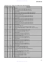
STR-KS1100
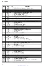
Pin No.
Pin Name
I/O
Description
49
MD0
I
CPU operation mode setting signal input terminal
50
MD1
I
Setting terminal for the CPU operation mode Fixed at "H" in this set
51
MD2
I
CPU operation mode setting signal input terminal
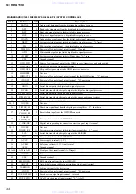
52
RDS CLK
I
RDS serial data transfer clock signal input from the tuner (FM/AM)
53
RDS DATA
I
RDS serial data input from the tuner (FM/AM)
54
SIRCS
I
SIRCS signal input from the remote control receiver
55
ADCC_INT
I
Auto digital cinema calibration interrupt signal input terminal
56
POWER KEY
I
Power key input terminal
57
NO USE
-
Not used
58
LAT2
O
Latch control signal output to the stream processor
59
TV LED
O
LED rive signal output of the TV indicator "H": LED on
60
SA-CD LED
O
LED rive signal output of the SA-CD/CD indicator "H": LED on
61
SHIFT
O
Shift clock signal output to the stream processor
62
SCDT
O
Serial data output to the stream processor
63
SOFT_MUTE
O
Soft muting on/off control signal output to the stream processor "L": muting on
64
INT
O
Reset signal output to the stream processor "L": reset
65
LAT1
O
Latch control signal output to the stream processor
66
NO USE
-
Not used
67
TUNER LED
O
LED drive signal output of the TUNER indicator "H": LED on
68
OVF
I
Over flow detection signal input from the stream processor "L": over flow
69
LAT3
O
Latch control signal output to the stream processor
70
VOLB
I
Jog dial pulse input from the rotary encoder (for MASTER VOLUME) (A phase input)
71
VOLA
I
Jog dial pulse input from the rotary encoder (for MASTER VOLUME) (B phase input)
72
FL_DIN
O
Serial data output to the fluorescent indicator tube
73
FL_CLK
O
Serial data transfer clock signal output to the fluorescent indicator tube
74
FL_STB
O
Strobe signal output to the fluorescent indicator tube
75
NO USE
-
Not used
76
DC_SD
I
DC shut down signal input terminal "L": shut down
77
RSTX
I
System reset signal input from the reset signal generator "L": reset
For several hundreds msec. after the power supply rises, "L" is input, then it change to "H"
78
OVFW
I
Over flow detection signal input from the stream processor "L": over flow
I
Sub system clock input terminal Not used
Sub system clock output terminal Not used
-
Ground terminal
I
Main system clock input terminal (24 MHz)
Main system clock output terminal (24 MHz)
-
Power supply terminal (+3.3V)
PLL serial data transfer clock signal output to the tuner (FM/AM)
PLL serial data output to the tuner (FM/AM)
87
SLATCH
O
Latch control signal output to the tuner (FM/AM)
88
T_DO
I
PLL serial data input from the tuner (FM/AM)
89
T_MUTE (NC)
O
Tuner muting on/off control signal output terminal Not used
90
ST (NC)
I
FM stereo detection signal input terminal Not used
91
P.CONT3
O
Power on/off control signal output terminal "H": power on
92
LRCK_SW
O
DSP clock selection signal output terminal Not used
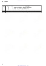
93
XMODE
O
System reset signal output to the digital audio interface receiver "L": reset
94
CKSEL1
O
Output clock selection signal output to the digital audio interface receiver
95
CLK
O
Serial data transfer clock signal output to the digital audio interface receiver
www. xiaoyu163. com
QQ 376315150
9
9
2
8
9
4
2
9
8
TEL 13942296513
9
9
2
8
9
4
2
9
8
0
5
1
5
1
3
6
7
3
Q
Q
TEL 13942296513 QQ 376315150 892498299
TEL 13942296513 QQ 376315150 892498299


