


44
STR-KS1100
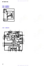
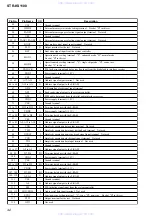
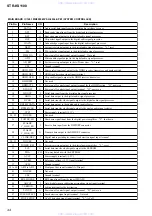
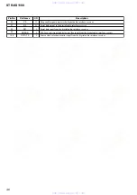
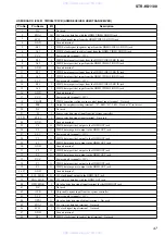
MAIN BOARD IC1601 MB90F045PF-G-9036-SPE1 (SYSTEM CONTROLLER)
Pin No.
Pin Name
I/O
Description
1
DATA0
I
Audio serial data input from the digital audio interface receiver
2
GP9
I
Read ready signal input from the digital audio signal processor
3
BST
O
Boot strap signal output to the digital audio signal processor
4
HCS
O
Chip select signal output to the digital audio signal processor
5
HACN
I
Acknowledge signal input from the digital audio signal processor
6
XRST
O
System reset signal output to the digital audio signal processor "L": reset
7
PM
O
PLL initialize signal output to the digital audio signal processor
8
PWM_DA
O
Power on/off control signal output terminal Not used
9
GP12
O
Write enable signal output to the digital audio signal processor
10
AD_RST
O
System reset signal output to the A/D converter "L": reset
11
VSS
-
Ground terminal
12
HDMI-SW1
O
Source selection signal output to the HDMI receiver/transceiver and analog switch
13
HDMI-DET
I
HDMI jack detection signal input terminal
14
HDMI-OEB
O
Chip enable signal output to the HDMI receiver/transceiver
15
HDMIPRE
-
Not used
16
HDMI-CTL
O
Power on/off control signal output terminal for the HDMI section "H": power on
17
P-CONT2
O
Power on/off control signal output terminal "H": power on
18
HDOUT
I
Serial data input from the digital audio signal processor
19
HDIN
O
Serial data output to the digital audio signal processor
20
HCLK
O
Serial data transfer clock signal output to the digital audio signal processor
21
BD3842 DATA
O
Serial data output to the analog audio input selector
22
BD3842 CLK
O
Serial data transfer clock signal output to the analog audio input selector
23
VCC5
-
Power supply terminal (+3.3V)
24, 25
NO USE
-
Not used
26
POWER_SD
I
Shut down signal input from the digital power amplifier "L": shut down
27
FLASH2/
C_LINK_RX
I
Receive data input from the DMPORT connector
28
FLASH1/
C_LINK_TX
O
Transmit data output to the DMPORT connector
29
C_LINK-DEC
I
Digital media port adapter connection detection signal input terminal
System reset signal output to the digital power amplifier "L": reset
Serial data transfer clock signal output to the EEPROM
Two-way data bus with the EEPROM
Reference voltage (+3.3V) input terminal
Front panel key input terminal (A/D input)
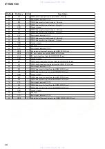
42
VSS
-
Ground terminal
43
RDS SIGNAL
I
RDS signal input from the tuner (FM/AM)
44
ADCC2
I
Auto digital cinema calibration microphone signal input terminal
45
VERSION
I
Setting terminal for the destination
46
P.CONT1
O
Power on/off control signal output terminal "H": power on
47
FUSE DETECT
I
Fuse detection signal input terminal Not used
48
STOP P.STOP
I
AC off detection signal input terminal "L": AC off
www. xiaoyu163. com
QQ 376315150
9
9
2
8
9
4
2
9
8
TEL 13942296513
9
9
2
8
9
4
2
9
8
0
5
1
5
1
3
6
7
3
Q
Q
TEL 13942296513 QQ 376315150 892498299
TEL 13942296513 QQ 376315150 892498299


