1-16
65
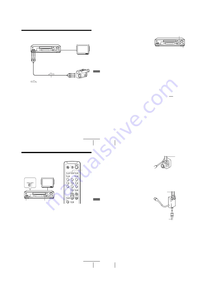
Editing with another VCR
A
d
ditio
nal Op
er
atio
ns
Editing with another VCR
How to connect to record on this VCR
Notes
• Make sure you connect the plugs to jacks of the same color.
• If you connected this VCR to both the LINE IN and LINE OUT jacks of the other VCR,
select the input correctly to prevent a humming noise.
• If the other VCR is a monaural type and connected to this VCR’s LINE-2 IN jacks, connect
the audio plug to the AUDIO L (white) jack. The sound is recorded on both right and left
channels. If you connect to the AUDIO R (red) jack, the sound is recorded only on the right
channel.
• You can use the LINE-1 IN jacks for editing. If the other VCR is a monaural type, the sound
is recorded only on the channel whose jack is connected to the audio plug. To record on both
right and left channels, connect the audio plugs to the AUDIO R/L jacks using a VMC-
910HG audio/video cable (not supplied).
This VCR (Recorder)
Other VCR (Player)
LINE OUT
: Signal flow
LINE-2 IN
TV
Audio/video cable (not supplied)
continued
66
Editing with another VCR
Operation (when recording on this VCR)
To stop editing
Press the
x
STOP buttons on both VCRs.
Tip
• To cut out unwanted scenes while editing, press
X
PAUSE on this VCR when an unwanted
scene begins. When it ends, press
X
PAUSE again to resume recording.
Note
• If you start recording following the procedure above, the VCR won’t start recording with the
APC function. To record a tape with the APC function, press
z
REC again during recording
pause in step 3 so that the VCR analyzes the tape. Then, press
X
PAUSE after the APC
indicator stops flashing to start recording. If you press
X
PAUSE before the APC indicator
stops flashing, the APC function is canceled.
Before you start editing
• Turn on your TV and set it to the
video channel.
• Press INPUT SELECT or
C/– to display “L2” (or
“L1”) in the display window.
• Press SP/EP to select the tape speed,
SP or EP.
1
Insert a source tape with its safety tab removed into the other (playback) VCR.
Search for the point to start playback and set it to playback pause.
2
Insert a tape into this (recording) VCR. Search for the point to start recording
and press
X
PAUSE.
3
Press
z
REC on this VCR to set it to recording pause.
4
To start editing, press the
X
PAUSE buttons on both VCRs at the same time.
z
REC
X
PAUSE
67
General setup information
Ad
dition
al I
n
fo
rm
atio
n
Additional Information
General setup information
Setting the RF unit
When connecting the VCR to the TV using
only the antenna cable, you must set the RF
UNIT switch on the rear of the VCR so that
the TV can receive the correct signal from
the VCR.
1
Set the RF UNIT switch on the rear of the VCR to CH3 or CH4, whichever
channel is not used in your area. If both are used, set the switch to either channel.
2
Press
?
/
1
POWER to turn on the VCR.
3
Press TV/VIDEO to turn on the VIDEO indicator in the VCR’s display window.
4
Press C/– to display a channel number in the display window.
Select an active channel number in your area.
5
Turn on your TV and set it to the channel you selected in step 1 (channel 3 or 4).
The channel you selected in step 4 appears on the TV screen. If the channels
change when you press C/–, you have made the correct setting.
Whenever you use the VCR, set the TV to the channel selected in step 1.
CH3
RF UNIT
CH4
TV
C/–
?
/
1
POWER
1
2
3
4
5
6
7
8
9
0
TV/VIDEO
continued
68
General setup information
Attaching the external antenna connector
Attaching a UHF/VHF band mixer
When using a 300-ohm twin lead cable for a
VHF/UHF antenna, use the EAC-32 antenna
connector (not supplied) to connect the
antenna to the VCR.
1
Loosen the screws on the antenna connector.
2
Wind the twin leads around the screws on the antenna connector.
3
Retighten the screws.
When using both a 75-ohm coaxial cable and
a 300-ohm twin lead cable for a VHF/UHF
antenna, use the EAC-66 UHF/VHF band
separator/mixer (not supplied) to connect the
antenna to the VCR.
1
Loosen the screws on the mixer.
2
Wind the twin leads around the screws on the mixer.
3
Retighten the screws.
4
Connect the 75-ohm coaxial cable to the mixer.
300-ohm twin
lead cable
EAC-32 antenna
connector (not
supplied)
300-ohm twin
lead cable
EAC-66
UHF/VHF
band
separator/
mixer (not
supplied)
75-ohm coaxial
cable
Содержание SLV-LX80S
Страница 28: ...SLV LX80S 3 1 3 2 SECTION 3 BLOCK DIAGRAMS 3 1 OVERALL BLOCK DIAGRAM ...
Страница 30: ...SLV LX80S 3 3 SERVO SYSTEM CONTROL BLOCK DIAGRAM 90 89 87 95 79 80 39 36 43 3 5 3 6 ...
Страница 31: ...SLV LX80S 3 4 TUNER BLOCK DIAGRAM 3 7 3 8 ...
Страница 32: ...SLV LX80S 3 5 AUDIO BLOCK DIAGRAM MA 397 BOARD SEE PAGE 4 13 T380 6 REC 50Vp p 69 9kHz TU701 3 9 3 10 ...
Страница 33: ...SLV LX80S 3 6 POWER BLOCK DIAGRAM CHILEAN MEXICAN 3 11 3 12E ...


