background image

COLOR CCD CAMERA

User Guide

38

COLOR CCD CAMERA

User Guide

39

Press the SET button in the EXIT menu to save the current settings and exit the SET menu.

EXIT

  DIS (Digital Image Stabilizer) :  

This function mitigates any picture movement due to external factors such as wind.

How to Use the Camera

• The chance of resolution decrease is existed because DIS function uses the digital zoom.
• DIS doesn’t operate when background illumination is too low.
• DIS doesn’t operate when object pattern is monotonic as like sky or white wall.
•  If Digital Image Stabilizer (DIS) is enabled, the digital zoom is not configured to less 

than 46 level.

Notes

  ❶  

When the SPECIAL menu screen is displayed, press the Up and Down buttons 
so that the arrow indicates ’COMM ADJ‘.

  2 


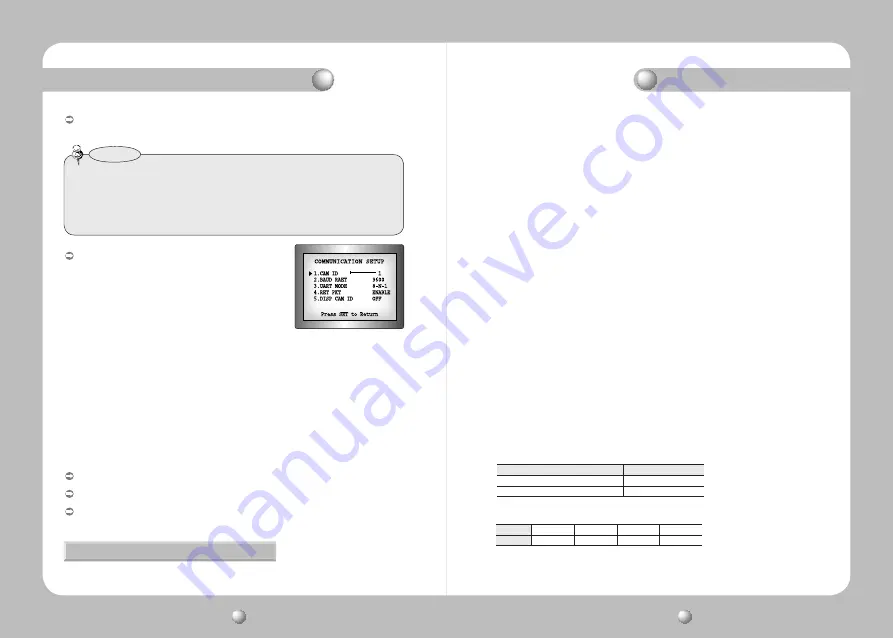
Set up the mode using the 4 direction buttons.


- CAM ID : Determines the camera's identification number (between 0 and 25).


- BAUD RATE : You can select 2400/4800/9600/19200/38400/57600 bps.


- UART MODE : You can select NONE, EVEN or ODD for the parity bits.


- RET PKT :  Determines whether to send a command back to the controller device 

when a communication control command is sent to the camera.


- DISP CAM ID : Display camera title on top left corner of the screen.

 LANGUAGE : You can select the menu language according to your requirements.
 RESET : Resets the camera settings to the factory defaults.
 RETURN :  Select this to save the SPECIAL menu settings and return to the SPECIAL 

menu.


COMM ADJ (Communication Adjustment) :


This function sets up the camera communication 
status when controlling the camera through an 
external control device.

Troubleshooting 

If you have trouble operating your camera, refer to the following table. If the 
guidelines do not enable  you to solve the problem, contact an authorized technician.

Nothing appears on the screen.

•  Check that the power cord and line connection between the camera and monitor are fixed properly.
•   Check that you have properly connected VIDEO cable to the camera VIDEO output jack.

The image on the screen is dim.

•  Is lens stained with dirt? Clean your lens with soft, clean cloth.
•  Set the monitor to proper condition.
•  If the camera is exposed to too strong light, change the camera position.

The image on the screen is dark.

•   Adjust the contrast feature of the monitor or DVR.
•  If you have an intermediate device, set the 75

Ω

 / Hi-z properly. 

The camera is not working properly, and the surface of the camera is hot.

•  Check that you have properly connected the camera to an appropriate power source.

The DAY/NIGHT menu does not work.

•  Check that AGC of EXPOSURE SETUP menu is 

OFF

.

The SENS-UP function does not work.

•  Check that AGC of EXPOSURE SETUP menu is 

OFF

.

•  Check that SHUTTER of EXPOSURE SETUP menu is 

A.FLK

 or 

MANUAL

.

The Motion Detection function does not work.

•  Check that MOTION DEF of SPECIAL SETUP menu is 

OFF

.

Color is not correct.

•    Check the setting of WHITE BAL SETUP menu .

The screen flickers continually.

•    Check that direction of camera turns toward the Sun.

RS-485 communication fails.

•    Check the polarity between RS-485 Control Port and RS-485 cable.

•    Check the RS-485 Communication establishment initial value

•  We recommend that you make ground connect between camera and controller in order to 

maintain safety communication control.

 485 Control Board Connection Port 

RS-485 Control Port

  (+) CONNECTION TERMINAL (TRX+) 

485+

  ( - ) CONNECTION TERMINAL (TRX-) 

485-

* RS-485 Communication establishment initial value

Item

Initial value

  Camera ID 

BAUD RATE  UART MODE 

RET PKT


9600 

8-NONE-1 

ENABLE

Содержание SCH-735

Страница 1: ...Supreme Resolution WDR Camera SHC 735 User Guide Before installing and operating this product please read this manual thoroughly ENGLISH ...

Страница 2: ...vironment This equipment generates uses and can radiate radio frequency energy and if not installed and used in accordance with the instruction manual may cause harmful interference to radio communications Operation of this equipment in a residential area is likely to cause harmful interference in which case the user will be required to correct the interference at his own expense WARNING Changes o...

Страница 3: ...or Connecting Power Control via RS 485 Interface 6 Precautions 8 Components and Accessories 10 Overview 11 11 12 13 14 Installation Procedures 15 18 19 20 15 How to Use the Camera 21 21 21 22 23 25 26 29 30 32 33 38 Troubleshooting 39 Specifications 40 Function Menu Structure How to Set up the Functions LENS EXPOSURE WHITE BALANCE BACKLIGHT SSNR DAY NIGHT IMAGE ADJ SPECIAL EXIT Contents ...

Страница 4: ... Wide Dynamic Range WDR By adopting a proprietary SV IV DSP chip the camera delivers clear high quality pictures even in backlight by increasing exposure in dark areas while decreasing it in bright areas a corrected image with clear details results SSNR Samsung Super Noise Reduction Function The high performance SV IV DSP chip dramatically reduces the gain noise in digital image processing produci...

Страница 5: ...ns is the most important component of the camera Be careful not to smear it with fingerprints Do not drop the camera or subject it to physical shock May cause a product malfunction Never keep the camera face to strong light directly May damage the CCD Do not expose the camera to radioactivity Radioactivity exposure may damage the CCD Do not expose the camera to rain or other types of liquids Wipe ...

Страница 6: ...Connector Plug 3 C MountAdapter 4 Instruction Manual Front View Overview Components and Accessories Tripod Mounting Bracket Screw Hole Used to fix theTripod Mounting Bracket to the top of the camera 2 C Mount Lens Adapter Install this adapter to use a C Mount Lens 3 Back Focus Control Lever Adjust focus by this Back Focus Lever 2 3 ...

Страница 7: ...a on a bracket or tripod The screw sizes for this hole are as follows 1 4 20 UNC 20 THREAD L 4 5mm 0 2mm ISO standard or 0 197 ASA standard L You can separate theTripod Mounting Bracket and install it on the top or bottom of the camera Make sure to use theTripod Mounting Bracket when fixing the camera to a bracket or tripod Otherwise the camera may not be secure or the internal circuitry of the ca...

Страница 8: ...o move the cursor left or right in the menu screen or to change the value of the selected item 7 D N Input Port You can switch to Day Night Mode by connecting an external signal to this port 8 MD Output Port Motion detection signals are output through this port 9 RS 485 Control Port You can control SETUP MENU through this port by using external controllers like a Remote controller that RS 485 Comm...

Страница 9: ...hen Using a CS Mount Lens Remove the protective glass cover at the front of this product and turn the CS Mount Lens clockwise to install it And set focus of camera using Back Focus Control Lever of camera side after combining CS Mount lens When Using C CS Mount Lens C Mount Lens 10mm or less CS Mount Lens 5mm or less 3 Remove the cover of the auto iris lens connector plug and solder the lens cable...

Страница 10: ...nd monitor Monitor When Using a C Mount Lens 1 Remove the protective glass cover at the front of this product and turn the C Mount Adapter clockwise to install it 2 Turn the C Mount lens clockwise to install it 3 Set focus of camera using Back Focus Control Lever of camera side after combining C Mount lens Installation Procedures Connecting a Monitor Connecting Power Since power specifications dif...

Страница 11: ...y long adaptor output line for connection to the camera may affect the performance of the camera Standard voltage for camera operation DC 12V 10 AC 24V 10 There may be some deviation in voltage drop depending on the type of wire and the manufacturer When the resistance value of copper wire is at 20ºC 68ºF You can set up functions using the 5 buttons on the rear of the camera UP button SET button L...

Страница 12: ...elect the connected lens type by using the Left and Right buttons LENS DC Video SelectAuto Iris Lens When DC is selected you can control screen brightness The range of brightness control is between 1 and 70 Adjust the brightness appropriately for optimal screen brightness Some lenses may not work properly depending on the setting of the BRIGHTNESS LEVEL When Using a Video Type Auto Iris Lens Disab...

Страница 13: ...use it in conjunction with the WDR mode of the BACKLIGHT menu When the SHUTTER is set to ESC after selecting the Internal Synchronization Type the picture may become unstable if the camera faces a bright fluorescent light Therefore take care when choosing the installation position When you use DC lens set the shutter mode to fixed if Color Rolling is occurred When the SHUTTER is set to MANUAL orA ...

Страница 14: ...by using the Up and Down buttons so that the arrow indicates BACKLIGHT BACKLIGHT White Balance may not work properly under the following conditions In this case select theAWC mode Whenthecolortemperatureofenvironmentsurroundingthesubjectisoutofthe controlrange e g clear sky or sunset 2 When the ambient illumination of the subject is dim 3 If the camera is directed towards a fluorescent light or is...

Страница 15: ...nce In a dark environment the HLC is only activated when a high light that is larger than a certain area is present The HLC is not activated in light or overly dark conditions Notes This function reduces the background noise in a low luminance environment 1 When the SETUP menu screen is displayed select SSNR by using the Up and Down buttons so that the arrow indicates SSNR 2 Select a desired mode ...

Страница 16: ...60s DURATION You can select brightness of illumination about changing the day night mode EXTERN This mode allows you to apply a desired filter to external signals When using a Video Auto Iris Lens if you set the lens level to low automatic switching between Color and Black White may not occur You cannot control the DAY NIGHT menu when AGC in the EXPOSURE menu is OFF At this time the exchange betwe...

Страница 17: ... Select this to save the settings for the IMAGE ADJ menu and to return to the SETUP menu PED LEVEL Please use this menu item when using a LCD monitor other than standard ones You can change PED LEVEL When theV REV or H REV mode is enabled the text on the screen does not flip If you increase the SHARPNESS level too high the picture may become distorted or noise may appear Notes 1 When the SETUP men...

Страница 18: ...tton all the letters are deleted To edit a letter change the cursor to the bottom left arrow and press the SET button Move the cursor over the letter to be edited move the cursor to the letter to be inserted and then press the SET button Notes Camera ID A B C D E F G H I J K L M N O P Q R S T U V W X Y Z a b c d e f g h i j k l m n o p q r s t u v w x y z 1 2 3 4 5 6 7 8 9 CLR POS END 5 Enter a ti...

Страница 19: ...ower synchronization function Line Lock without using a synchronization signal generator INT Internal SynchronizationType L L Power SynchronizationType Line lock Press the SET button You can select a desired phase from 0 to 359 when select phase You can decide the synchronization between luminance and color signal when select the mode When the SPECIAL menu screen is displayed press the Up and Down...

Страница 20: ...amera refer to the following table If the guidelines do not enable you to solve the problem contact an authorized technician Nothing appears on the screen Check that the power cord and line connection between the camera and monitor are fixed properly Check that you have properly connectedVIDEO cable to the cameraVIDEO output jack The image on the screen is dim Is lens stained with dirt Clean your ...

Страница 21: ...Internal Line Lock Frequency H 15 734KHz V 59 94Hz H 15 625KHz V 50 00Hz Horizontal Resolution COLOR 560TV lines Min B W 700TV lines Min Min Illumination COLOR 0 3Lux 50 IRE F1 2 0 001Lux SENS UP x256 B W 0 01Lux 50 IRE F1 2 0 00004Lux SENS UP x256 S N Y Signal 52dB AGC Off Weight On Video Output CVBS 1 0Vp p 75Ω OPERATIONAL IRIS Adustment DC VIDEO Electronic Shutter Speed ESC Manual A FLK Fixed N...

Страница 22: ...COLOR CCD CAMERA User Guide 42 COLOR CCD CAMERA User Guide 43 MEMO MEMO ...

Страница 23: ...COLOR CCD CAMERA User Guide 44 COLOR CCD CAMERA User Guide 45 MEMO MEMO ...

Страница 24: ...COLOR CCD CAMERA User Guide 46 COLOR CCD CAMERA User Guide 47 MEMO MEMO ...

Страница 25: ...i do Korea 462 703 TEL 82 31 740 8151 8 FAX 82 31 740 8145 SAMSUNG TECHWIN AMERICA Inc 1480 Charles Willard St Carson CA 90746 UNITED STATES Tol Free 1 877 213 1222 FAX 1 310 632 2195 SAMSUNG TECHWIN EUROPE CO LTD Samsung House 1000 Hillswood Drive Hillswood Business Park Chertsey Surrey KT16 OPS TEL 44 1932 45 5300 FAX 44 1932 45 5325 SALES NETWORK ...

Отзывы: