background image

66

SCD-C222ES

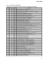
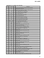
Pin No.

Pin Name

I/O

Description

54

HINT

O

Not used (pull up)

55

XS16

O

Not used (pull up)

56

HA1

I

Not used (fixed at “H” )

57

XPDI

I/O

Not used (pull up)

58

VDDS

Power supply terminal (+5V)  (digital system)

59, 60

HA0, HA2

I

Not used (fixed at “H” )

61

VSS

Ground terminal (digital system)

62, 63

HCS0, HCS1

I

Not used (open)

64

VDD

Power supply terminal (+3.3V)  (digital system)

65

DASP

I/O

Not used (pull up)

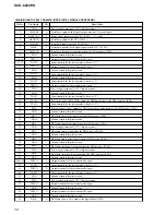
66 to 69

MDB0 to MDB3

I/O

Two-way data bus with the D-RAM (IC706)

70

VSS

Ground terminal (digital system)

71

MDB4

I/O

Two-way data bus with the D-RAM (IC706)

72

VDD5V

Power supply terminal (+5V)

73 to 75

MDB5 to MDB7

I/O

Two-way data bus with the D-RAM (IC706)

76

XMWR

O

Write enable signal output to the D-RAM (IC706)

77

VDD

Power supply terminal (+3.3V)  (digital system)

78

XRAS

O

Row address strobe signal output to the D-RAM (IC706)

79, 80

MA0, MA1

O

Address signal output to the D-RAM (IC706)

81

VSS

Ground terminal (digital system)

82 to 87

MA2 to MA7

O

Address signal output to the D-RAM (IC706)

88

VDD

Power supply terminal (+3.3V)  (digital system)

89

MA8

O

Address signal output to the D-RAM (IC706)

90

VSS

Ground terminal (digital system)

91

MA9/MNT0

O

Address signal output to the D-RAM (IC706)

92

MA10/MNT1

O

RF data signal output terminal    Not used (open)

93

MA11/MNT2

O

Operation clock signal output for PSP physical disc mark detection to DSD decoder (IC801)
Monitor signal output to the CPU (IC901)

94

XMOE

O

Output enable signal output to the D-RAM (IC706)

95

XCAS

O

Column address strobe signal output to the D-RAM (IC706)

96, 97

MDB8, MDB9

I/O

Two-way data bus with the D-RAM (IC706)

98

VSS

Ground terminal (digital system)

99

MDBA

I/O

Two-way data bus with the D-RAM (IC706)

100

VDD

Power supply terminal (+3.3V)  (digital system)

101, 102

MDBB, MDBC

I/O

Two-way data bus with the D-RAM (IC706)

103

VDD5V

Power supply terminal (+5V)

104 to 106 MDBD to MDBF

I/O

Two-way data bus with the D-RAM (IC706)

107

GFS

O

Guard frame sync signal output to the CPU (IC901)

108

VSS

Ground terminal (digital system)

109

APEO

O

Absolute phase error signal output

110

VDD

Power supply terminal (+3.3V)  (digital system)

111

DASYO

O

RF binary signal output

112

GNDA5

Ground terminal (analog system)

113, 114

ASF1, AFS2

Filter connected terminal for selection the constant asymmetry compensation

115

DASYI

I

Analog signal input after integrated from the RF binary signal

116

RFDCC

I

Input terminal for adjusting DC cut high-pass filter for RF signal    Not used (open)

117

RFIN

I

RF signal input from the CXD1881R (IC001)

Содержание SCD-C222ES - Es Series 5 Disc

Страница 1: ...limit 0 001 W PEAK or less Output connector Jack type Output level Load impedance ANALOG OUT Phono 2 Vrms Over 10 kilohms jacks at 50 kilohms DIGITAL CD Square 18 dBm OUT OPTICAL optical output connector DIGITAL CD Coaxial 0 5 Vp p 75 ohms OUT COAXIAL output connector PHONES Stereo 10 mW 32 ohms phone jack Output only the audio signals of the CD Lightemitting wave length 660 nm General Laser Semic...

Страница 2: ...iring Board MAIN Board Component Side 40 6 12 Printed Wiring Board MAIN Board Conductor Side 41 6 13 Schematic Diagram MAIN Board 1 5 42 6 14 Schematic Diagram MAIN Board 2 5 43 6 15 Schematic Diagram MAIN Board 3 5 44 6 16 Schematic Diagram MAIN Board 4 5 45 6 17 Schematic Diagram MAIN Board 5 5 46 6 18 Schematic Diagram AUDIO HEADPHONE Boards 47 6 19 Printed Wiring Board AUDIO Board Component Si...

Страница 3: ...hods 1 A commercial leakage tester such as the Simpson 229 or RCA WT 540A Follow the manufacturers instructions to use these instruments 2 A battery operated AC milliammeter The Data Precision 245 digital multimeter is suitable for this job 3 Measuring the voltage drop across a resistor by means of a VOM or battery operated AC voltmeter The limit indica tion is 0 75 V so analog meters must have an...

Страница 4: ...ctive lens LASER DIODE AND FOCUS SEARCH OPERATION CHECK Carry out the S curve check in CD section adjustment and check that the S curve waveforms is output three times CLEANING OF OPTICAL PICK UP LENS In cleaning the lens of optical pick up use the air blower Never use a cotton swab for cleaning the lens of optical pick up which otherwise causes a trouble CHECKING SIGNALS OF CD SECTION Efficiency ...

Страница 5: ... Focus search 8 Focus servo on 9 Spindle kick 10 Spindle servo on 11 E F balance auto adjustment 12 Tracking sled servo on 13 Focus bias auto adjustment 14 Focus servo gain auto adjustment 15 Tracking servo gain auto adjustment 16 Jump to lead in area 17 Read TOC 18 Stop 3 SACD dual layer 1 Sled reverse move sled in 2 Disc detect 3 IC setting for SACD 4 Servo error signal offset auto adjustment 5 ...

Страница 6: ...yer the LED turns on and CD layer the LED turns off qh MULTI CHANNEL DECODING indicator Turns on when you turn on the player or when the Multi channel Super Audio CD is loaded and select the Multi channel playback area by pressing MULTI 2CH qj Disc tray 11 Press A OPEN CLOSE to open close the disc tray qk TIME TEXT button 13 Each time you press the button the playing time of the track the total re...

Страница 7: ... AMS AMS Automatic Music Sensor buttons 16 Press to locate a specific track 0 m M buttons 17 Press to locate a portion you want to play within a track qa DISC SKIP buttons 16 Press to select the disc qs CD1 2 COMMAND MODE switch 6 Select the command mode qd DISPLAY MODE button 13 Press to turn off the information qf SACD CD button 12 Each time you press the button while the Hybrid disc page 10 is ...

Страница 8: ...Page 11 3 5 AUDIO BOARD Page 10 3 5 AUDIO BOARD Page 10 3 7 MAIN BOARD Page 11 3 4 CD MECHANISM DECK CDM59A DVBU5A Page 10 3 4 CD MECHANISM DECK CDM59A DVBU5A Page 10 3 10 SENSOR BOARD Page 13 3 11 LOADING MOTOR BOARD Page 13 SET Note 1 The process described in can be performed in any order Note 2 Without completing the process described in the next process can not be performed Note 3 Illustration...

Страница 9: ...crews flat head 3 case 2 screw flat head 1 two screws flat head 5 connector CN601 8 claw 7 three screws 3 8 6 screw BVTP3 8 9 front panel section Note When removing the loading panel refer to Section 1 Servicing Notes on page 4 1 loading panel assy 8 claw 4 connector CN881 2 wire flat type 12 core CN706 3 connector CN104 ...

Страница 10: ...sy 2 Insert a tapering driver from the bottom of the chassis and turn it in the direction of the arrow until the base unit goes down to the lowest position 7 9 CD mechanism deck CDM59A DVBU5A a a 1 connector CN705 3 4 CD MECHANISM DECK CDM59A DVBU5A 3 5 AUDIO BOARD 7 AUDIO board 6 clamp 2 connector CN301 1 wire flat type 19 core CN701 1 wire flat type 19 core CN702 3 connector CN704 5 two screws B...

Страница 11: ... BOARD 6 POWER board 7 four washers 4 four screws BVTP3 8 3 connector CN707 5 two clamps 2 connector CN301 1 connector CN151 1 connector CN105 3 connector CN705 4 MAIN board 1 connector CN705 3 clamp 1 connector CN707 2 four screws BVTP3 8 ...

Страница 12: ... 9 TABLE ASSY Note When installing the table assy on the chassis assy engage the gear loading C with the groove by looking into the gear through a hole in the table assy qs table assy 9 three screws BTTP M2 6 q clamp e c c d d e qa bracket guide gear loading C 7 two screws BTTP M2 6 5 screw BTTP M2 6 6 bracket guide 2 two screws BTTP M2 6 1 Slide the tray until the screw that fixes the bracket gui...

Страница 13: ...10 SENSOR BOARD 3 11 LOADING MOTOR BOARD 1 screw PTPWH M2 6 3 belt rotary 4 two screws BTTP M2 6 4 two screws BTTP M2 6 5 SENSOR board 2 tray 3 two screws BTTP M2 6 4 LOADING MOTOR board 1 belt loading 2 connector CN13 ...

Страница 14: ...hrough under the chassis and engage its dowel with the groove of rotary encoder 2 Install the rotary encoder so that its groove comes to the position shown in the figure 1 Insert the shaft gear up to the position where its shaft comes out by 5 mm g g h h f f f 7 gear U D 8 screw PTPWH M2 6 q screw PTPWH M2 6 circle mark circle mark swing gear gear RV Fig A 9 gear RV Note Align swing gear a circle ...

Страница 15: ...pe 1 Category Application MODEL SATD S5 12 cm disc Adjusted value check J 2501 215 A SL Reference disc Operation check SATD S4 Optical waveform check J 2501 184 A Not specified DL 12 cm disc Operation check PATD 012 Adjusted value check 4 225 203 01 CD 12 cm disc Operation check YEDS 18 Reference disc Optical waveform check 3 702 101 01 Not specified HYBRID 12 cm disc Operation check 1 SL Single L...

Страница 16: ...o related No Name Description Remarks 41 TGAIN NM UP The tracking servo gain is switched between normal and up Normal or up are switched alternately 44 ADJ TRK DSP The traverse AGC and E F balance adjustment is performed 45 TRACKING AGC The tracking servo gain is adjusted automatically SEARCH command 5X Track search related Nos 51 through 53 are not used for the servicing No Name Description Remar...

Страница 17: ...ified number of times or until an error occurred 95 DISP ERROR The content of error recorded to the set is read and displayed Refer to Error Display list page 26 Error recording Only one item is recorded 96 D OUT OnOff Digital out of CD is turned on or off Not used in this set 98 APDD JITTER Not used for the servicing 9C BU DENCHO The content of error recorded to the set is read and then the S cur...

Страница 18: ...CHECK and press the AMS dial to enter 3 When 10 TOTAL CHECK is displayed rotate the AMS dial clockwise by 2 clicks to select 12 MANUAL CHK and press the AMS dial to enter 4 When 120 MANUAL CHK is displayed rotate the AMS dial clockwise by 4 clicks to select 124 READ TOC PSP and press the AMS dial to enter 5 A checking will start automatically Note In making a check the disc must be loaded Immediat...

Страница 19: ...ted CN701 702 and FFC connection is loose or FFC is disconnected DVD DRAM ERR 1 IC706 D RAM is faulty 2 IC701 pin znv XRST does not go H IC901 pin ts XDIS does not go H IC902 expander is faulty 3 Faulty communication line between IC701 and IC706 Data line address line WE etc 4 D903 1SS367 is faulty D 3 3V is not present to IC706 CD DSP ERROR 1 IC509 CD DSP is faulty 2 768fs 33 86688 MHz is not pre...

Страница 20: ...et 0 RF 8 bit data in hex notation RF A0h VC FE TE 9 bit data in hex notation VC FE TE 00h RF VC FE TE ADJ Offset values after RF PI VC FE TE signal offset adjustment VC offset is not adjusted Less than ORG value if offset correction is normal Measurement only RF 8 bit data in hex notation Also for SACD the TE offset is VC FE TE 9 bit data in hex notation not measured and adjusted PI TRVS PP ORG A...

Страница 21: ...e 1 SACD Use the test disc SATD S5 or SATD S4 Note Measured values in check items are typical ones Check items Specified value LOAD IN TIME msec Not displayed in this set SPIN UP TIME msec 1993 1800 to 2450 PF VC FE TE AVRG ORG 8E E 1E2 12 RF 91 C8 VC 1F8 8 FE 1D1 30 TE 198 75 PF VC FE TE AVRG ADJ 9D E 6 2 RF 91 AF VC 1F8 8 FE 1EE 12 TE 1EA 16 PI TRVS PP ORG ADJ 80 129 100 90 PI ORG 80 100 PI ADJ ...

Страница 22: ...c or less R AVE MIN MAX msec 824 661 920 AVE 1200 msec or less MAX 1300 msec or less 1 MAX SEEK TIME 311660 0 _ 311660 F AVE MIN MAX msec 1991 1964 2015 AVE 2200 msec or less MAX 2500 msec or less R AVE MIN MAX msec 1711 1701 1726 AVE 2200 msec or less MAX 2500 msec or less ERROR RATE C1 MAX AVE 3 0 C1 MAX 15 or less C2 MAX AVE 0 0 C2 MAX 0 HENSHIN RYOU 1 10um 168 800 or less 100 um or less SPIN D...

Страница 23: ...d of 5 allows the check ing to be repeated by the set number of times Also setting 0 zero allows the aging check to be repeated until an error oc curs 5 4 HYBRID DISC OPERATION CHECK Perform as necessary This test checks the auto adjustment time required when the disc is switched between HD SACD layer and CD layer This test is conducted to check the stability in switching from CD to SACD or SACD t...

Страница 24: ...t specification a mes sage ng is displayed next to the measurement value 7 When you want to repeat the test press AMS again 8 Press the OPEN CLOSE key to terminate the test and re move the disc 1 The measurement can be performed without placing a disc However the BU chucking time and unchucking time will be slightly different from the actual values 2 When the machine enters this mode once it canno...

Страница 25: ...he key turn the AMS dial and then press the CONTINUE key The program does not advance if these keys are not pressed in the above sequence 3 The panel door repeats opening and closing 4 The messages AP B 000000 during open t AP C 000000 during close are repeated on the FL display Num ber of times of open close are displayed in decimal number in 000000 with OPEN CLOSE as a set 5 Press the key to ter...

Страница 26: ...ription of display An error code is displayed in From From 1 means retry failed 3 times From 2 means abnormal value Optical pick up RF amplifier or CD DSP IC is faulty FCS AGC ERROR Error at focus gain automatic adjustment Defocusing during adjustment Optical pick up RF amplifier or CD DSP IC is faulty TRK AGC ERROR Error at tracking gain automatic adjustment Defocusing during adjustment Optical p...

Страница 27: ...is pressed the check mode is switched in order for S curve waveformt traverse waveformtRF waveform Setting Method After setting the test mode rotate the AMS dial to select 9C BU DENCHO and press the AMS dial to enter BU MEASURE will be displayed if the BU electrical adjust ment mode becomes active S Curve Check Connection Checking Method 1 After setting the BU electrical adjustment place the test ...

Страница 28: ...s the AMS dial 2 Connect an oscilloscope to the TP703 RFAC and TP704 AGND on the MAIN board 3 After WAIT is displayed the RF waveform check mode will become active and PLAY 5th TRACK will be displayed and the 5th music on the disc will be played 4 Check that the RF waveform is clear and the level satisfies the specification 5 Press the AMS dial and OUTSIDE TRACK will be displayed and the outward t...

Страница 29: ...SCD C222ES 29 29 TP506 FE TP513 TE TP516 RFCK TP704 AGND TP703 RFAC TP808 DG TP517 WFCK TP504 AVC IC509 IC701 IC801 IC703 Checking and Connecting Location MAIN Board Component Side ...

Страница 30: ... 18 23 33 34 20 22 21 19 8 40 41 39 43 31 32 29 30 20 SLED MOTOR DRIVE FOCUS TRACKING COIL DRIVER SLED MOTOR DRIVER IC502 M M M2 SLED 8 9 SPINDLE MOTOR DRIVE M M M3 SPINDLE 8 9 LOADING MOTOR DRIVE M M M10 LOADING 15 16 17 13 FOCUS TRACKING SLED PWM GENERATOR FFDR FRDR TFDR TRDR SFDR SRDR SERVO INTERFACE SERVO AUTO SEQUENCER A D CONVERTER FOCUS TRACKING SLED SERVO DSP DFCT FOK DETECTOR 26 SE TE FE ...

Страница 31: ...B0 MDB7 DASYO DASYI ASF1 ASF2 WPK XRAS XMWR MA11 MNT2 DBCK XSAK XSHD XDCK XSAQ WPK XTAL HDB0 HDB7 HDB8 HDB9 HDBA HDBF HA0 HA2 HDRQ XHRS XHAC XHWR XHRD HCS1 HCS0 HINT REDY SIGNAL PATH SACD PLAY CD PLAY ANALOG OUT CD PLAY DIGITAL OUT ATAPI PACKET FIFO ATAPI REGISTER DMA FIFO DAC INTERFACE CD ESP OE UCAS WE RAS LCAS A0 A9 I O8 I O15 I O0 I O7 D RAM IC706 AUTHENTICATION CPU INTERFACE DMA CONTROLLER XT...

Страница 32: ...TCH AMUTZ A1 IN T SENS XCS IO XDIS IO MODE DF PWE RXD TXD EEPSIO EEPSCL RST SDEN XCS XDIS RST DSD LIM SW RST DVD RST CD XRD XWR A0 A2 D0 D7 LOAD IN LOAD OUT I O EXPANDER IC902 XRST CD DSL DSR DSLS DSRS DSC DSLF E64FSO E128FSO DATA SHIFT LATCH AMUTZ D0 D7 A0 A2 XHRD XHWR LOAD IN OUT TBLL TBLR VMOD 166 165 167 168 XASK XSHD XDCK XSAQ 126 WARFI REAC WPK 2 3 5 6 8 9 11 12 139 136 134 131 21 24 27 32 2...

Страница 33: ...IGITAL FILTER D A CONVERTER IC302 1 DSDL 2 DSDR 20 DBCK 4 PDATA 5 PLRCK 3 PBCK DSD INTERFACE PCM INTERFACE DSD FILTER PCM FILTER 18 PSCK 19 DSCK MUX MULTI LEVEL DELTA SIGMA MODULATOR ANALOG LOW PASS FILTER MULTI LEVEL D A CONVERTER MODE CONTROL 15 MD 16 MC 17 MS 9 VOUTL 10 VOUTR DATA SHIFT LATCH DIGITAL FILTER D A CONVERTER IC303 1 DSDL 2 DSDR 20 DBCK 4 PDATA 5 PLRCK 3 PBCK DSD INTERFACE PCM INTER...

Страница 34: ...04 SACD CD LED DRIVE Q804 D803 MULTI CHANNEL DECODING LED DRIVE Q701 702 GRID DRIVE Q801 802 FL801 FLUORESCENT INDICATOR TUBE VF1 VF2 MUTE 3 3V D 3 3V IC811 3V IC304 DAC 5V IC301 303 3 3V REGULATOR IC310 5V REGULATOR IC903 AU 7V IC305 307 7V REGULATOR IC905 HP UR IC309 RECT D924 925 AU 7V IC305 307 7V REGULATOR IC904 RECT D922 923 HP UR IC309 CDM 10V LOADING TABLE MOTOR DRIVE IC11 RECT D151 152 VF...

Страница 35: ... unless otherwise specified f internal component 5 fusible resistor C panel designation A B Line B B Line Voltages and waveforms are dc with respect to ground under no signal conditions no mark SACD PLAY CD PLAY Impossible to measure Voltages are taken with aVOM Input impedance 10 MΩ Voltage variations may be noted due to normal produc tion tolerances Waveforms are taken with a oscilloscope Voltag...

Страница 36: ...LOCK KHM 230AAA 1 680 791 11 11 E E E E RF BOARD CONDUCTOR SIDE 1 680 791 11 11 A B C D 1 2 3 4 5 C034 C019 C014 L002 L001 L003 IC001 IC004 6 7 PRINTED WIRING BOARD RF Board See page 35 for Circuit Boards Location Semiconductor Location Ref No Location D001 D 4 D002 D 4 IC001 B 3 IC004 D 4 Q001 B 4 Q002 B 5 Q003 B 4 Q005 B 5 Page 40 ...

Страница 37: ...10V 10 10 10V 2SB1121 ST TD 10 10 10V 47 6 3V 47 6 3V 2200p 2200p 2200p 2200p 1000p 0 0 330p 0 1 30P DVD_PD CD_PD RFP DVD_PD CD_PD CD_LD SP SP LIM_SW SD SD SP SP LIM_SW SD SD TD TD A B C D VMOD DVD_LD FD FD FD FD TD TD CD_F CD_E LDON MIRR D3V D3V SDEN DATA_RF CLK_RF FE PI FE E G H F VMOD PI MIRR VMOD FE PI TE PI SDEN DATA_RF CLK_RF LDON FE TE DVD_LD VMOD CD_LD B RFP C D A E H F G CD_F CD_E VMOD DV...

Страница 38: ...SCD C222ES 38 38 MAIN BOARD CN705 TABLE SENSOR DISC SENSOR 1 4 3 2 F IC11 6 9 PRINTED WIRING BOARDS MOTOR SENSOR Section See page 35 for Circuit Boards Location Page 40 ...

Страница 39: ...SCD C222ES 39 39 6 10 SCHEMATIC DIAGRAM MOTOR SENSOR Section See page 59 for IC Block Diagram Page 46 ...

Страница 40: ...801 IC814 IC703 IC503 IC901 IC803 E POWER BOARD CN904 F JUNCTION BOARD CN11 CN705 1 13 C960 S902 WFCK RFCK RFAC DG AGND FE AVC TE FLASH WRITING WRITING IMPOSSIBLE R WRITING POSSIBLE 6 11 PRINTED WIRING BOARD MAIN Board Component Side See page 35 for Circuit Boards Location Semiconductor Location Ref No Location IC503 H 4 IC509 C 3 IC701 C 6 IC703 A 7 IC801 C 9 IC803 G 9 IC814 D 8 IC901 G 6 Page 36...

Страница 41: ...502 IC903 IC802 IC902 IC504 IC905 IC512 FL903 R812 Q703 Q704 E E 6 12 PRINTED WIRING BOARD MAIN Board Conductor Side See page 35 for Circuit Boards Location Semiconductor Location Ref No Location D903 A 4 D904 A 2 IC502 F 9 IC504 G 9 IC512 H 10 IC702 E 3 IC706 B 4 IC708 B 6 IC802 H 5 IC808 C 3 IC811 E 5 IC812 E 4 IC813 D 4 IC902 G 6 IC903 G 4 IC905 I 9 Q701 J 7 Q702 J 7 Q703 J 6 Q704 J 6 ...

Страница 42: ...M 470k 0 1 0 10 10V 0 1 MNT2 MNT3 GND 0 1 0 10k 10k 33k 33k 0 0 1 22 16V 0 1 0 1 0 1 10 10V 10 10 0 1 0 10k 4 7k 3 3k 0 4 7k 0 10k 2 2k 3 3k 1 6k 0 1 10k 0 1 47k 1k 2200p 0 047 0 1k 2200p 2200p 1000p 0 1 10 10V 10k 10k 68k BA5983FP 0 1 10 10 0 1 0 1 0 1 10 10 0 2 7k 680p 2 7k 680p 3 3k 0 47 680p 22k 10k 3 3k 0 47 680p 22k 1 0 0 1 10 10V 0 NJM3404AM TE2 220k 0 1 10 10V 220k 1 10k 1 0 1 10 10V 22 10...

Страница 43: ... 10V 0 1 47k 47k 0 1 22 1 3300p 0 1 10k 220p 10k 10k 0 01 0 1 2 2k 0 1 100 10k 0 1 68k 1M 1000p 33p 0 1 0 01 0 1 100k 1 10 10V 100k 10k 10 10V BCK MDATA LRCK 0 1 0 100p 0 1 0 1 100k 0 1 C2PO 0 0 0 0 047 0 47 8 2k 2 2k 0 1 22k 1M 0 1 22k 0 1 10 10V 0 1 10 10V 0 1 0 1 220k 100k 100k 1500p 10 10V 1500p 0 1 220k NJM3404AM TE2 10 10V 47k 4700p 100 10k 0 47 1k 100 0 10k 0 0 01 0 0 0 0 2 2k SPIN DVC AGND...

Страница 44: ...SN74LV245APWR SN74LV245APWR WM RF 100 0 033 22 0 0 0 01 DG 0 01 A1 A2 A3 A4 A5 A6 A7 A8 1C 2C 3C 4C 5C 6C 7C SD7 SD6 SD5 SD4 SD3 SD2 SD1 SD0 SHRRDY XMSLAT XRST_DSD RF_AC XSHD SDCK XSHD XSAK SDEF D3V DGND XDCK SHRMUT A1IN A1OUT DOUT AV0 AV1 AV2 AV3 AV4 AV5 AV6 AV7 SDEF XSAK XSAK SDEF XSHD SDCK AV0 AV1 AV2 AV3 AV4 AV5 AV6 AV7 XSRQ SA0 SA1 SA2 SA3 SA4 SA5 SA6 SA7 SA8 SA9 SA10 SA11 SCAS SRAS SWE DCLK ...

Страница 45: ...940 R910 R1022 R930 R929 R928 R926 R820 1k 1k 1000p 10k 10k 1000p 10k 1000p 10k 100 0 22 10k 1000p 0 01 10k 10k 100 100 22 0 0 01 10 10V 0 01 10k 10k 100 0 1 0 1 0 01 10k 10k 0 5 6k 0 0 01 0 01 10 10V 0 01 100 100 0 10k 1k 1 0 01 3 3k 0 01 100 6 3V 220 4V 220 4V 100 6 3V 47 16V 12P 8 2k M51957BFP 600C 10000p 10k 22 1k 22 22 22 22 22 22 22 10k 10k 10k 20MHz 100p 0 22 100 5P BR24C64F E2 1 1 1 1 0 CX...

Страница 46: ... 1 10 10V 10 10V 1 1 22 47 SN74LVU04A 0 1 2 2k CXD9647R 0 0 01 2 2k 22 100 0 01 100 100 47 CXD1095BR DTA143EKA T146 DTA143EKA T146 47 25V 13P 1C 2C 3C 4C 5C 6C 7C 3D 4D 5D 6D 7D 8D 9D 10D 11D 1D 2D A1 A0 D3 D4 D5 D7 D1 D2 D0 SA CD XRST_CD XRST_DVD XHRD XHWR XCS_IO XDIS_IO SOUT1 SCK1 D6 A2 T_SENS D_SENS OUT_SW_CHG S1 S2 TBLR LOAD_IN LOAD_OUT VMOD SDEN ISBTEST IFREQ SP_ON MUTE_LOAD KEY0 KEY1 KEY2 KE...

Страница 47: ...9k 3 9k 100p 100V 100p 100V 100 2SC3624A 3 9k 330 330 100k 100k 10k 6 2k 6 2k 10k NJM2114M TE2 NJM2114M TE2 330 3 9k 330 3 9k 100 100p 100V 100p 100V 3 9k 100 330 3 9k 330 100k 100k NJM2114M TE2 330p 100V 5 1k 5 1k 6 8k 10k 6 2k 6 2k 470p 100V 470p 100V 680p 100V 680p 100V 10k 10k 330p 100V 47 25V 5 1k 5 1k 47 25V 100000p 47 25V 47 25V 10k 10k 6 2k 6 2k 470p 100V 470p 100V 680p 100V 5 1k 5 1k 6 8k...

Страница 48: ...SCD C222ES 48 48 AUDIO BOARD COMPONENT SIDE 1 681 337 11 11 A B C D E F 1 2 3 4 5 6 19 PRINTED WIRING BOARD AUDIO Board Component Side See page 35 for Circuit Boards Location ...

Страница 49: ...510 R541 Q442 R561 R445 R443 R449 R442 R448 R451 R446 R444 Q542 R447 R450 R543 R545 R544 R546 R548 R550 Q541 R551 R549 R547 R542 R441 Q441 R521 Q422 R425 R423 R429 R422 R428 R431 R426 R424 Q522 R427 R430 R523 R525 R524 R526 R528 R530 Q521 R531 R529 R527 C339 R522 R421 Q421 C328 R399 R397 R398 1 1 3 2 3 4 5 E RV881 JW842 FB883 FB882 FB881 CN881 C882 C883 C881 L883 L882 L881 CONTROL A1II DIGITAL CD ...

Страница 50: ... CN104 LP803 CN807 IC802 R852 R851 1 C816 C817 3 CN812 S817 S818 S819 S820 S821 S816 S815 S814 S813 S812 R861 R862 R863 R864 R865 R866 R867 R868 1 3 2 4 CN804 D803 D803 C820 R818 1 2 ROTARY ENCODER DISPLAY BOARD 1 2 3 4 66 65 62 61 20 IC801 28 E E E E E 19 29 2 6 1 5 3 1 H X x SACD CD EX CHANGE DISC SKIP MULTI 2CH A OPEN CLOSE 1 682 030 11 11 G J 1 2 S806 811 l AMS L PUSH ENTER 1 682 035 11 11 RM ...

Страница 51: ... 3G 4G 5G 6G 7G 8G 9G 10G 11G 12G 13G 14G 15G KEY1 KEY0 KEY1 KEY0 KEY1 1 KEY1 1 S12 S13 S14 S15 S16 S17 S18 S19 S20 S21 S22 S23 S24 S25 S26 S27 S28 S29 S30 S31 S32 S33 S34 S1 S2 S3 S4 S5 S6 S7 S8 S9 S10 S11 S16 S15 S14 S13 S12 S20 S19 S18 S17 S21 S22 S23 S24 S25 S26 S27 S28 S29 S30 S31 S32 S33 S34 16G F1 F1 1 G 2G 3G 4G 5G 6G 7G 8G 9G 10G 11G 12G 13G 14G P35 P34 P33 P32 P31 P30 P29 P28 P27 P26 P25...

Страница 52: ...POWER BOARD CONDUCTOR SIDE CHASSIS E 1 1 1 10 2 1 1 2 3 2 3 1 2 3 2 1 3 2 1 3 2 1 3 1 1 9 12 E MAIN BOARD CN707 H AUDIO BOARD CN301 CHASSIS 1 681 338 11 11 L PT BOARD CN151 M PT BOARD CN152 K PT BOARD CN105 REG BOARD 1 682 159 11 11 POWER BOARD COMPONENT SIDE 1 681 338 11 11 A B C D E F G H 1 2 3 4 5 6 7 8 6 23 PRINTED WIRING BOARDS POWER REG Boards See page 35 for Circuit Boards Location Page 53 ...

Страница 53: ...601 C601 CN602 PT BOARD CONDUCTOR SIDE 1 1 2 3 1 10 1 1 1 2 2 2 1 2 4 J DISPLAY BOARD CN802 M POWER BOARD CN905 L POWER BOARD CN901 K POWER BOARD CN907 1 681 339 11 11 NOT REPLACEABLE BUILT IN TRANSFORMER POWER SW BOARD 1 682 032 11 11 1 2 1 2 POWER AC IN T150 POWER TRANSFORMER 1 2 3 1 2 2 1 6 24 PRINTED WIRING BOARDS POWER SW PT Boards See page 35 for Circuit Boards Location Page 52 Page 50 Page ...

Страница 54: ...12L5 EC10QS04 TE12L5 EC10QS04 TE12L5 EC10QS04 TE12L5 0 01 100V 0 01 100V 0 0 22000p 1k 1k 47 25V 0 01 100V 2200p 10k 10k 2200p 0 EC10DS2TE12L EC10DS2TE12L EC10DS2TE12L EC10DS2TE12L 0 1 33 2200p 10k 4700 16V 4700 16V 4700 25V 4700 25V EC10DS2TE12L EC10DS2TE12L EC10DS2TE12L EC10DS2TE12L 1000p 0 01 100V 1000p 2 2 33k 10 50V 6 8k 6 8k 3 3k 47 63V UDZ TE 17 33B EC10DS2TE12L UDZ TE 17 3 0B 3P 12P 4 7 4 ...

Страница 55: ...Board 1 IC001 el TE SACD Play mode 3 IC001 tj RFAC SACD Play mode 1 IC001 el TE CD Play mode 2 IC509 wg MDP CD Play mode 2 IC001 r FE SACD Play mode 3 IC001 tj RFAC CD Play mode 3 IC509 el FE IC901 yj FE PI SACD Play mode 2 IC001 r FE CD Play mode Approx 1 5 Vp p MAIN Board 1 IC509 0 WFCK IC701 zbz WFCK 3 IC509 el FE IC901 yj FE PI CD Play mode Approx 80 mVp p ...

Страница 56: ...E IC901 yg TE SACD Play mode 7 IC509 yj BCK IC701 zb BCLK CD Play mode 4 IC509 ra TE IC901 yg TE CD Play mode qa IC701 zzm RFIN CD Play mode 5 IC509 t RFAC SACD Play mode 8 IC509 ua XTAI qs IC701 znm XTAL 5 IC509 t RFAC CD Play mode 0 IC701 rk XDCK qf IC801 qa MCKI 2 6 Vp p 29 5 ns qa IC701 zzm RFIN SACD Play mode qd IC701 zm XTA1 6 IC509 yg LRCK IC701 znc LRCK CD Play mode 3 4 Vp p 22 7 µs 9 IC50...

Страница 57: ...1 tl BCKAI w IC901 ra EXTAL qh IC801 ya PHREFI wh IC803 of BCLK CD Play mode qj IC811 8 wa IC803 wk FS128 qk IC811 0 3 5 Vp p 354 ns 4 3 Vp p 29 5 ns ql IC811 qs ws IC803 e FS64 3 5 Vp p 177 ns wf IC803 ik MCKI 3 2 Vp p 29 5 ns wd IC803 ig DVCKI 3 4 Vp p 472 ns wg IC803 o LRCK CD Play mode 3 4 Vp p 22 7 µs wj IC803 og LRCKI CD Play mode ...

Страница 58: ...9 Vp p 88 6 ns 1 6 Vp p 540 ns 3 4 Vp p 88 6 ns 4 Vp p 88 6 ns 6 IC301 303 w DBCK 2 IC304 4 6 0 2 IC801 ta OSCI 3 IC304 8 7 IC301 303 qk PSCK ql DSCK 4 IC301 303 3 PBCK CD Play mode 5 IC301 303 5 PLRCK CD Play mode 4 Vp p 22 7 µs AUDIO Board 1 IC304 1 DISPLAY Board 1 IC801 t OSCO ...

Страница 59: ...LD GCA TOPHOLD GCA 41 48 47 46 45 GCA OFFSET CANSEL 5 FROM S PORT GCA 40 GCA OFFSET CANSEL 6 FROM S PORT 3 FROM S PORT GCA GCA CEFDB CP CN LOW IMPEDANCE CD DVD SUB GCA MUX GCA LPF GCA LPF 39 38 37 36 OFFSET CANSEL PEAK BOTTOM HOLD BOTTOM ENVELOPE INPUT BUFFER 5 FROM S PORT GCA LPF V25 2 TE RST 35 34 33 FOR SERVO OUTPUT PH TOP HOLD GCA SEL LINKEN MUX HOLDEN COMPA RATOR INTERNAL FDGHG HYSTERESISTER ...

Страница 60: ...LLER COVERNER LOAD CURRENT DETECTION AMPLIFIER COVERNER OUTPUT REFERENCE VOLTAGE OUTPUT LOW VOLTAGE OUTPUT RIN1 IOUT VEE VEE VCC VREF VREG VCC OUT1 OUT1 18 17 16 15 1 2 3 4 5 6 7 8 9 14 13 12 11 10 MAIN Board IC905 M51957BFP 600C JUNCTION Board IC11 BA6780 4 NC INPUT NC GND 1 25V 1 2 3 5 6 7 8 DELAY CAPACITOR OUTPUT SUPPLY VOLTAGE NC ...

Страница 61: ... 65 64 63 62 61 60 59 58 57 56 55 54 53 52 51 50 49 48 47 46 45 DESCRAMBLE RF ASYMMETRY HOST I F ATAPI OR DMA OR VIDEO DMA FIFO AUTHENTICATION INTERNAL CLOCK CD ESP GNDA2 GNDA1 SPO VC2 MDIN2 MDIN1 VCCA1 CLVS VSS MDSOUT VDD MDPOUT GSCOR EXCK SBIN VSS SCOR WFCK VDD5V XRCI VDDS C2PO VDD DBCK BCLK DDAT MDAT VSS DLRC LRCK IFS0 IFS1 XRST XTAL VSS XTL2 XTL1 D0 D1 D2 D3 D4 VDD DFCT LINK D5 D6 VSS D7 A0 VD...

Страница 62: ...C DIGITAL OUT EFM DEMODULATOR 32K RAM ERROR CORRECTOR D A DIGITAL INTERFACE MIRR DFCT FOK DETECTOR CPU INTERFACE SUBCODE PROCESSOR SERVO AUTO SEQUENCER SERVO INTERFACE DVDD0 XRST MUTE DATA XLAT CLOK SENS SCLK ATSK WFCK XUGF XPCK GFS C2PO SCOR C4M WDCK DVSS0 COUT MIRR AVDD0 IGEN AVSS0 ADIO RFDC CE TE AVSS1 RFAC ASYI ASYO BIAS AVDD1 PCO FILI FILO CLTV V16M VCTL VPCO 59 58 57 56 55 54 53 52 51 50 49 ...

Страница 63: ...C901 20 MIRR O Mirror signal output to the CPU IC901 21 DFCT I O Defect signal input output terminal Not used pull up 22 FOK O Focus OK signal output to the CPU IC901 23 PWMI I Spindle motor external control signal input terminal Not used fixed at L 24 LOCK O GFS is sampled by 460 Hz H output when GFS is H 25 MDP O Spindle motor M3 servo drive signal output to the CXD1882R IC701 26 SSTP I Detectio...

Страница 64: ...ut from the CPU IC901 L digital out off H digital out on 64 DOUT O Digital audio signal output to the DIGITAL CD OPTICAL OUT IC309 65 LRCK O L R sampling clock signal 44 1 kHz output to the CXD1882R IC701 and CXD9647R IC803 66 PCMD O Serial data output to the CXD1882R IC701 and CXD9647R IC803 67 BCLK O Bit clock signal 2 8224 MHz output to the CXD1882R IC701 and CXD9647R IC803 68 EMPH O L is outpu...

Страница 65: ...6 O Stream data signal output to the DSD decoder IC801 28 VDDS Power supply terminal 5V digital system 29 HDB9 O Not used open 30 HDB5 O Stream data signal output to the DSD decoder IC801 31 HDBA O Not used open 32 HDB4 O Stream data signal output to the DSD decoder IC801 33 VSS Ground terminal digital system 34 HDBB O Not used open 35 HDB3 O Stream data signal output to the DSD decoder IC801 36 V...

Страница 66: ...MNT0 O Address signal output to the D RAM IC706 92 MA10 MNT1 O RF data signal output terminal Not used open 93 MA11 MNT2 O Operation clock signal output for PSP physical disc mark detection to DSD decoder IC801 Monitor signal output to the CPU IC901 94 XMOE O Output enable signal output to the D RAM IC706 95 XCAS O Column address strobe signal output to the D RAM IC706 96 97 MDB8 MDB9 I O Two way ...

Страница 67: ...nal of internal CLV circuit 145 DEFECT I Defect signal input terminal Not used fixed at L 146 GSCOR I Guard subcode sync S0 S1 detection signal input from the CXD3068Q IC509 147 EXCK O Subcode serial data reading clock signal output to the CXD3068Q IC509 148 SBIN I Subcode serial data input from the CXD3068Q IC509 149 VSS Ground terminal digital system 150 SCOR I Subcode sync S0 S1 detection signa...

Страница 68: ...Pin No Pin Name I O Description 170 XTA1 I System clock input terminal 33 8688 MHz 171 VDD Power supply terminal 3 3V digital system 172 to 176 D0 to D4 I O Two way data bus with the CPU IC901 and I O expander IC902 ...

Страница 69: ... 27 TDI I Input terminal for the test normally open 28 VSC Ground terminal for core 29 TDO O Output terminal for the test normally open 30 TMS I Input terminal for the test normally open 31 TRST I Reset terminal for the test normally fixed at L 32 to 34 TEST1 to TEST3 I Input terminal for the test normally fixed at L 35 VDC Power supply terminal 2 5V for core 36 TESTO O Output terminal for the tes...

Страница 70: ... TESTO O Output terminal for the test normally open 80 VSC Ground terminal for core 81 82 TESTO O Output terminal for the test normally open 83 VDC Power supply terminal 2 5V for core 84 85 TESTO O Output terminal for the test normally open 86 VSIO Ground terminal for I O 87 TESTO O Output terminal for the test normally open 88 89 TESTI I Input terminal for the test normally fixed at L 90 VDIO Pow...

Страница 71: ...45 XRAS O Row address strobe signal output to the D RAM IC808 146 VDIO Power supply terminal 3 3V for I O 147 TESTO O Output terminal for the test normally open 148 149 A11 A10 O Address signal output to the D RAM IC808 150 VSC Ground terminal for core 151 152 A9 A8 O Address signal output to the D RAM IC808 153 VDC Power supply terminal 2 5V for core 154 to 157 A7 to A4 O Address signal output to...

Страница 72: ...decoder IC801 29 TESTI I Input terminal for the test normally fixed at L 30 FS64 O Phase reference signal output for DSD output phase modulation to the DSD decoder IC801 31 GND Ground terminal digital system 32 DSI1 I DSD data front L ch input from the DSD decoder IC801 33 GND Ground terminal digital system 34 DSI2 I DSD data front R ch input from the DSD decoder IC801 35 VDD Power supply terminal...

Страница 73: ...Not used 75 VDD Power supply terminal 3 3V digital system 76 GND Ground terminal digital system 77 TESTI I Input terminal for the test normally fixed at L 78 TESTI I Input terminal for the test Not used 79 XSBSL2 I HD mode selection signal input from the I O expander IC902 80 81 TESTI I Input terminal for the test Not used 82 XABSL1 I HD mode selection signal input from the I O expander IC902 83 8...

Страница 74: ...Serial data latch pulse signal output to the CXD3068Q IC509 28 A1IN I Sircs remote control signal input of the CONTROL A1II J381 29 COUT CD I Numbers of track counted signal input from the CXD3068Q IC509 30 IN SW I Loading in switch input terminal L loading in Not used fixed at H 31 OUT SW I Loading out switch input terminal L loading out Not used fixed at H 32 MIRR RF I Mirror signal input from t...

Страница 75: ...7 FE PI I Focus error signal input from the CXD1881R IC001 68 AVSS Ground terminal for A D converter 69 AVREF I Reference voltage input terminal for A D converter 70 AVDD Power supply terminal 3 3V for A D converter 71 GFS CD I Guard frame sync signal input from the CXD3068Q IC509 72 SCLK CD O SENSE serial data reading clock signal output to the CXD3068Q IC509 73 1 2 LD Not used open 74 FOK CD I F...

Страница 76: ...tial signal output to the digital filter Not used 98 LATCH DF O Latch signal output to the digital filter IC301 to IC303 99 SHIFT DF O Shift signal output to the digital filter IC301 to IC303 100 SCDATA DF O Serial data output to the digital filter IC301 to IC303 ...

Страница 77: ... to the CXD1882R IC701 L reset 21 RST CD O Reset signal output to the CXD3068Q IC509 L reset 22 VMOD O Power on off control signal output for modulation circuit on optical pick up block L power off H power on 23 VSS Ground terminal digital system 24 VDD Power supply terminal 3 3V digital system 25 MULTI O Multi 2ch selection signal output L 2ch H multi 26 SDEN O Serial data enable signal output to...

Страница 78: ... 58 PA3 PA4 Not used open 59 OUT SW I Disc tray open close detection switch S11 input terminal L disc tray open H disc trat close 60 PA6 Not used open 61 LIM SW I Detection signal input from limit in switch S1 The optical pick up is inner position when H 62 PB0 Not used open 63 64 NC Not used open ...

Страница 79: ...Indication of Appearance Parts Example KNOB BALANCE WHITE RED Parts Color Cabinet s Color Les composants identifiés par une marque 0 sont critiquens pour la sécurité Ne les remplacer que par une pièce portant le numéro spécifié The components identified by mark 0 or dotted line with mark 0 are critical for safety Replace only with part number specified Ref No Part No Description Remark Ref No Part...

Страница 80: ...4 4 230 721 01 WINDOW FL 65 X 4954 182 1 BASE INDICATOR ASSY PANEL 66 1 682 034 11 LED BOARD 67 4 230 722 01 BUTTON PLAY 68 A 4726 302 A DISPLAY BOARD COMPLETE 69 4 235 580 01 BUTTON OPEN CLOSE 70 X 4953 971 1 BUTTON INDICATOR ASSY 71 4 235 577 01 BASE R PANEL 72 1 682 033 11 HEADPHONE BOARD 73 3 354 931 11 KNOB DIA 10 74 4 235 590 01 ESCUTCHEON H P 75 1 690 892 11 WIRE FLAT TYPE 12 CORE 76 1 500 ...

Страница 81: ...114 1 682 159 11 REG BOARD 115 3 703 150 11 CLAMP 116 4 971 099 01 WASHER P 0T150 1 431 174 21 TRANSFORMER POWER 0T151 1 437 300 11 TRANSFORMER POWER 1 7 685 646 79 SCREW BVTP 3X8 TYPE2 N S The components identified by mark 0 or dotted line with mark 0 are critical for safety Replace only with part num ber specified Les composants identifiés par une marque 0 sont critiques pour la sécurité Ne les ...

Страница 82: ...ark Ref No Part No Description Remark 501 1 676 245 11 SENSOR BOARD 502 4 218 253 31 SCREW M2 6 BTTP 503 X 4924 457 1 ROLLER ASSY 504 4 224 602 01 TABLE 505 4 224 617 01 GEAR RM E 506 4 218 252 51 SCREW PTPWH M2 6 FLOATING 507 4 224 616 01 GEAR RM M 508 4 224 615 03 GEAR RM B 509 4 225 328 01 BELT ROTARY 510 4 224 603 01 TRAY 511 4 224 619 01 BRACKET GUIDE 512 3 703 150 11 CLAMP M11 A 4672 867 B M...

Страница 83: ...NG 562 4 224 611 01 GEAR LOADING B 563 3 016 533 01 WASHER FR STOPPER 564 4 951 619 21 CUSHION A 565 4 224 606 01 GEAR RV 566 4 224 605 01 GEAR U D 567 4 229 956 02 PLATE A CHUCKING 568 3 053 844 01 YOKE 569 4 229 957 01 PLATE B CHUCKING 570 4 224 618 01 LEVER LIFTER 571 1 791 930 11 WIRE FLAT TYPE 6 CORE 572 1 676 246 11 JUNCTION BOARD 575 4 218 252 51 SCREW PTPWH M2 6 FLOATING M10 A 4735 379 A M...

Страница 84: ...227 549 11 INSULATOR 0606 8 820 132 03 OPTICAL PICK UP KHM230AAA J1RP 607 1 757 097 11 WIRE FLAT TYPE 25 CORE 608 A 4726 887 A RF BOARD COMPLETE The components identified by mark 0 or dotted line with mark 0 are critical for safety Replace only with part num ber specified Les composants identifiés par une marque 0 sont critiques pour la sécurité Ne les remplacer que par une pièce portant le numéro...

Страница 85: ...ide film resistor F nonflammable Items marked are not stocked since they are seldom required for routine service Some delay should be anticipated when order ing these items SEMICONDUCTORS In each case u µ for example uA µA uPA µPA uPB µPB uPC µPC uPD µPD CAPACITORS uF µF COILS uH µH C402 1 136 811 11 FILM 330PF 5 100V C403 1 136 356 11 FILM 470PF 5 100V C404 1 130 892 00 FILM 0 015uF 5 63V C405 1 ...

Страница 86: ...00 METAL CHIP 220 5 1 10W L403 1 216 033 00 METAL CHIP 220 5 1 10W L404 1 414 553 11 FERRITE 0uH L501 1 216 033 00 METAL CHIP 220 5 1 10W L502 1 216 033 00 METAL CHIP 220 5 1 10W L503 1 216 033 00 METAL CHIP 220 5 1 10W L504 1 414 553 11 FERRITE 0uH TRANSISTOR Q301 8 729 027 35 TRANSISTOR DTA143TKA T146 Q302 8 729 120 28 TRANSISTOR 2SC1623 L5L6 Q303 8 729 027 35 TRANSISTOR DTA143TKA T146 Q381 8 72...

Страница 87: ...11 CARBON MELF 10K 2 1 8W R505 1 259 932 11 CARBON MELF 6 2K 2 1 8W R506 1 260 020 11 CARBON MELF 100K 2 1 8W R507 1 259 989 11 CARBON MELF 330 2 1 8W R508 1 259 989 11 CARBON MELF 330 2 1 8W R509 1 216 065 00 RES CHIP 4 7K 5 1 10W R510 1 259 983 11 CARBON MELF 100 2 1 8W R511 1 259 983 11 CARBON MELF 100 2 1 8W R512 1 216 065 00 RES CHIP 4 7K 5 1 10W R513 1 216 105 00 RES CHIP 220K 5 1 10W R514 1...

Страница 88: ... CHIP 33K 5 1 10W SWITCH ROTARY ENCODER S804 1 570 101 51 SWITCH KEY BOARD SACD CD S805 1 570 101 51 SWITCH KEY BOARD MULTI 2CH S806 1 771 349 21 SWITCH KEYBOARD A OPEN CLOSE S807 1 771 349 21 SWITCH KEYBOARD H S808 1 771 349 21 SWITCH KEYBOARD X S809 1 771 349 21 SWITCH KEYBOARD x S810 1 771 349 21 SWITCH KEYBOARD EX CHANGE S811 1 771 349 21 SWITCH KEYBOARD DISC SKIP S830 1 476 100 11 ENCODER ROT...

Страница 89: ...C528 1 125 822 11 TANTALUM 10uF 20 10V C529 1 164 739 11 CERAMIC CHIP 560PF 5 50V C530 1 107 826 11 CERAMIC CHIP 0 1uF 10 16V C531 1 165 176 11 CERAMIC CHIP 0 047uF 10 16V C532 1 107 826 11 CERAMIC CHIP 0 1uF 10 16V C533 1 162 966 11 CERAMIC CHIP 0 0022uF 10 50V C534 1 162 970 11 CERAMIC CHIP 0 01uF 10 25V C535 1 162 966 11 CERAMIC CHIP 0 0022uF 10 50V C536 1 125 891 11 CERAMIC CHIP 0 47uF 10 10V ...

Страница 90: ...78 1 164 156 11 CERAMIC CHIP 0 1uF 25V C779 1 125 822 11 TANTALUM 10uF 20 10V C780 1 125 822 11 TANTALUM 10uF 20 10V C781 1 125 822 11 TANTALUM 10uF 20 10V C790 1 126 204 11 ELECT CHIP 47uF 20 16V C791 1 126 206 11 ELECT CHIP 100uF 20 6 3V C792 1 126 206 11 ELECT CHIP 100uF 20 6 3V C793 1 126 246 11 ELECT CHIP 220uF 20 4V C794 1 126 246 11 ELECT CHIP 220uF 20 4V C795 1 126 206 11 ELECT CHIP 100uF ...

Страница 91: ...R FFC FPC 19P CN702 1 778 691 11 CONNECTOR FFC FPC 19P CN704 1 815 348 11 PIN CONNECTOR PC BOARD 6P CN705 1 794 804 11 PIN CONNECTOR PC BOARD 13P CN706 1 784 371 21 CONNECTOR FFC FPC 12P CN707 1 815 347 11 PIN CONNECTOR PC BOARD 12P CN708 1 784 386 21 CONNECTOR FFC FPC 30P CN709 1 793 687 11 PIN CONNECTOR 1 5mm SMD 5P DIODE D903 8 719 049 09 DIODE 1SS367 T3SONY D904 8 719 049 09 DIODE 1SS367 T3SON...

Страница 92: ...0 11 METAL CHIP 100K 0 5 1 16W R544 1 218 740 11 METAL CHIP 100K 0 5 1 16W R545 1 218 740 11 METAL CHIP 100K 0 5 1 16W R549 1 216 864 11 METAL CHIP 0 5 1 16W R554 1 216 826 11 METAL CHIP 2 7K 5 1 16W R555 1 218 704 11 METAL CHIP 3 3K 0 5 1 16W R556 1 216 826 11 METAL CHIP 2 7K 5 1 16W R558 1 216 841 11 METAL CHIP 47K 5 1 16W R559 1 216 797 11 METAL CHIP 10 5 1 16W R560 1 216 821 11 METAL CHIP 1K 5...

Страница 93: ... 11 METAL CHIP 10K 5 1 16W R755 1 216 864 11 METAL CHIP 0 5 1 16W R756 1 216 864 11 METAL CHIP 0 5 1 16W R757 1 216 864 11 METAL CHIP 0 5 1 16W R758 1 216 864 11 METAL CHIP 0 5 1 16W R759 1 216 864 11 METAL CHIP 0 5 1 16W R761 1 218 700 11 METAL CHIP 2 2K 0 5 1 16W R762 1 218 724 11 METAL CHIP 22K 0 5 1 16W R763 1 218 714 11 METAL CHIP 8 2K 0 5 1 16W R764 1 216 857 11 METAL CHIP 1M 5 1 16W R765 1 ...

Страница 94: ...1 216 801 11 METAL CHIP 22 5 1 16W R938 1 216 801 11 METAL CHIP 22 5 1 16W R939 1 216 809 11 METAL CHIP 100 5 1 16W R940 1 216 809 11 METAL CHIP 100 5 1 16W R941 1 216 809 11 METAL CHIP 100 5 1 16W R942 1 216 809 11 METAL CHIP 100 5 1 16W R943 1 216 809 11 METAL CHIP 100 5 1 16W R944 1 216 833 11 METAL CHIP 10K 5 1 16W R945 1 216 833 11 METAL CHIP 10K 5 1 16W R946 1 216 833 11 METAL CHIP 10K 5 1 1...

Страница 95: ...47uF 20 25V C961 1 163 033 00 CERAMIC CHIP 0 022uF 50V DIODE D902 8 719 210 33 DIODE EC10DS2 D903 8 719 977 81 DIODE DTZ33B D906 8 719 210 33 DIODE EC10DS2 D907 8 719 210 33 DIODE EC10DS2 D908 8 719 210 33 DIODE EC10DS2 D909 8 719 210 33 DIODE EC10DS2 D910 8 719 210 33 DIODE EC10DS2 D911 8 719 210 33 DIODE EC10DS2 D912 8 719 210 33 DIODE EC10DS2 D913 8 719 210 33 DIODE EC10DS2 D918 8 719 210 39 DI...

Страница 96: ...0 25V C013 1 164 172 11 CERAMIC CHIP 0 0056uF 10 25V C014 1 117 370 11 CERAMIC CHIP 10uF 10V C015 1 117 370 11 CERAMIC CHIP 10uF 10V C016 1 164 218 11 CERAMIC CHIP 180PF 0 25PF 50V C017 1 162 919 11 CERAMIC CHIP 22PF 5 50V C018 1 162 919 11 CERAMIC CHIP 22PF 5 50V C019 1 117 370 11 CERAMIC CHIP 10uF 10V C020 1 162 919 11 CERAMIC CHIP 22PF 5 50V C021 1 162 919 11 CERAMIC CHIP 22PF 5 50V C022 1 115 ...

Страница 97: ... 5 1 16W R023 1 216 864 11 METAL CHIP 0 5 1 16W R024 1 216 864 11 METAL CHIP 0 5 1 16W R025 1 216 864 11 METAL CHIP 0 5 1 16W R029 1 216 841 11 METAL CHIP 47K 5 1 16W R035 1 216 864 11 METAL CHIP 0 5 1 16W R036 1 216 833 11 METAL CHIP 10K 5 1 16W R044 1 216 832 11 METAL CHIP 8 2K 5 1 16W R046 1 218 668 11 METAL CHIP 100 0 5 1 16W R065 1 218 716 11 METAL CHIP 10K 0 5 1 16W R066 1 218 716 11 METAL C...

Страница 98: ...151 1 437 300 11 TRANSFORMER POWER M10 A 4735 379 A MOTOR ASSY LOADING M11 A 4672 867 B MOTOR ASSY ROTARY TRAY ACCESSORIES PACKING MATERIALS 1 476 601 11 REMOTE COMMANDER RM SC500 1 590 925 31 CORD CONNECTION RED AND WHITE AUDIO CONNECTING CORD 1 757 960 21 CORD CONNECTION BLACK AUDIO CONNECTING CORD 1 777 241 11 CORD CONNECTION MONAURAL MINI PLUG CORD 4 228 696 01 COVER BATTERY for RM SC500 4 235...

Страница 99: ...99 SCD C222ES MEMO ...

Страница 100: ...STORY Clicking the version allows you to jump to the revised page Also clicking the version at the upper right on the revised page allows you to jump to the next revised page Ver Date Description of Revision 1 0 2001 07 New ...

Отзывы: