


6-1
6. ALIGNMENT AND ADJUSTMENTS
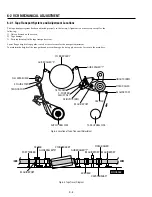
6-1 VCR ADJUSTMENT
6-1-1 Reference
1) X-Point (Tracking center) adjustment, “Head switching adjustment” and “NVRAM option setting” can be adjusted with remote control.
2) When replacing the Main PCB Micom (IC601) and NVRAM (IC603: EEPROM) be sure to adjust the “Head switching adjustment” and
“NVRAM option setting”.
3) When replacing the cylinder ass’y, be sure to adjust the “X-Point” and “Head switching adjustment”.
4) How to adjustment.
- Intermittently short-circuit the Test Point on Main PCB with pincers to the adjustment mode.
- If the corresponding adjustment button is pressed, the adjustment is performed automatically.
- When the adjustment is completed, be sure to turn the power off.
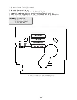
6-1-1(a) Location of adjustment button of remote control
SLV-D350P/D550P
X-Point (Tracking Center) Adjustment ;
Head Switching Adjustment ;
Fig. 6-1
Содержание RMT-V501C
Страница 10: ... 10 MEMO ...
Страница 43: ...2 3 Fig 2 7 Circuit Board Locations 2 2 CIRCUIT BOARD LOCATIONS DVD MAIN PCB FUNCTION PCB VCR MAIN PCB ...
Страница 67: ...3 BLOCK DIAGRAM 3 2 3 1 SLV D350P D550P ...
Страница 68: ...3 4E MEMO ...
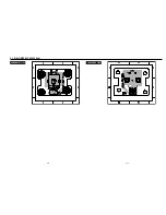
Страница 70: ...4 3 4 4 4 1 VCR MAIN FUNCTION TIMER COMPONENT SIDE ...
Страница 71: ...4 6 4 5 CONDUCTOR SIDE ...
Страница 72: ...4 7 4 8 COMPONENT SIDE CONDUCTOR SIDE 4 2 DVD MAIN ...
Страница 73: ...4 10 4 9 4 3 DIAL TIMER SLV D550P Only COMPONENT SIDE CONDUCTOR SIDE ...
Страница 74: ...4 12E MEMO ...
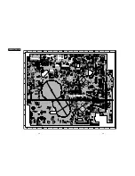
Страница 76: ... BLOCK IDENTIFICATION OF MAIN PCB 5 3 5 4 Component Side Conductor Side VCR MAIN PCB ...
Страница 77: ...5 1 S M P S 5 6 5 5 ...
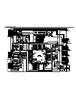
Страница 78: ...5 2 POWER DRIVE 5 7 5 8 ...
Страница 79: ...5 3 LOGIC FUNCTION TIMER 5 10 5 9 ...
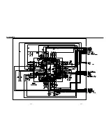
Страница 80: ...5 4 A V 5 11 5 12 ...
Страница 81: ...5 5 Hi Fi MTS 5 14 5 13 ...
Страница 82: ...5 6 INPUT OUTPUT 5 15 5 16 ...
Страница 83: ...5 7 DVD 5 18 5 17 ...
Страница 84: ...MEMO 5 20E ...
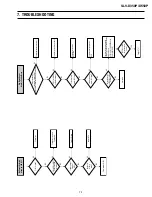
Страница 112: ...7 18E MEMO ...