


1-14
61
A/V Receiver hookup
Ad
v
a
n
ce
d Hoo
kups
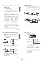
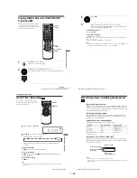
Advanced Hookups
A/V Receiver hookup
A
Use this hookup if your A/V receiver has a Dolby* Surround (Pro
Logic) decoder and 3 to 6 speakers
You can enjoy the Dolby Surround effects only when playing Dolby Surround audio
or multi-channel audio (Dolby Digital) discs.
∗
Manufactured under license from Dolby Laboratories. “Dolby,” “Pro Logic,” and the double-
D symbol are trademarks of Dolby Laboratories.
Note
• When connecting 6 speakers, replace the monaural rear speaker with a center speaker, 2 rear
speakers and a subwoofer.
DVD-VCR
Front (R)
Front (L)
Rear (R)
Subwoofer
l
: Signal flow
Rear (L)
Amplifier (receiver) with Dolby
Surround decoder
Center
Rear (mono)
Stereo audio cord
(not supplied)
[Speakers]
(red)
(white)
[Speakers]
to audio input
(white)
(red)
to LINE OUT L/R (AUDIO)
continued
62
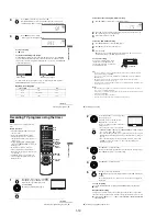
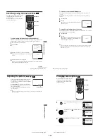
A/V Receiver hookup
B
Use this hookup if your A/V receiver has a Dolby Digital or DTS*
decoder, a digital input jack and 6 speakers
This connection will allow you to use the Dolby Digital or DTS decoder function of
your AV amplifier (receiver). You are not able to enjoy the surround sound effects of
this player. You must make connections using
and
.
∗
“DTS” and “DTS Digital Out” are trademarks of Digital Theater Systems, Inc.
Note
• After you have completed the connection, be sure to set “Dolby Digital” to “Dolby Digital”
and “DTS” to “On” in “AUDIO SETUP” menu (page 65). Otherwise, no sound or a loud
noise will come from the speakers.
B-1
B-2
1
Front (R)
Front (L)
Rear (R)
AV amplifier (receiver) having
a decoder
Subwoofer
Center
[Speakers]
DVD-VCR
[Speakers]
Rear (L)
to coaxial or optical
digital input
and
Coaxial digital
cord (not supplied)
l
: Signal flow
Stereo audio
cord (not
supplied)
(red)
(white)
to audio input
(white)
(red)
to LINE OUT L/R (AUDIO)
or
to DIGITAL AUDIO OUT
(COAXIAL or OPTICAL)
Optical digital cord (not
supplied)
Remove jack cap
before connecting
63
S-Video/Component Video hookup
Ad
v
a
n
ce
d Hoo
kups
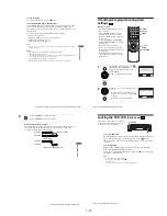
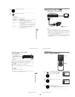
S-Video/Component Video hookup
Make audio connections using the LINE OUT AUDIO L/R jacks or DIGITAL AUDIO OUT
(OPTICAL or COAXIAL) jacks on the right side of the DVD-VCR when you use S-VIDEO/
Component Video hookup.
A
Use this hookup if your TV has an S-VIDEO input jack
Connect an S-VIDEO cord (not supplied). You will enjoy high quality images.
Notes
• The connection using S-VIDEO OUT jack is only for the DVD player.
• If you set “Progressive” to “On” in the “SCREEN SETUP” menu, S-Video playback may be
distorted.
l
: Signal flow
(DVD only)
TV or AV amplifier
TV
S-VIDEO cord
(not supplied)
DVD-VCR
Audio cord
(not supplied)
Coaxial
digital cord
(not supplied)
Optical digital
cord (not
supplied)
Remove jack
cap before
connecting
or
or
to coaxial or optical
digital input
to audio
input
continued
64
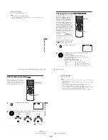
S-Video/Component Video hookup
B
Use this hookup if your TV has component video input jacks
Connect your TV via the COMPONENT VIDEO OUT jacks using a component
video cord (not supplied) or three video cords (not supplied) of the same kind and
length. You will enjoy accurate color reproduction and high quality images.
See page 61 for audio connections.
If your TV accepts progressive (480p) format signals, you must use this connection
and then set “Progressive” to “On” in the “SCREEN SETUP” menu (page 67). The
PROGRESSIVE indicator lights up in orange when the DVD player outputs
progressive signals.
Notes
• The connection using COMPONENT VIDEO OUT jack is only for the DVD player.
• Consumers should note that not all high definition television sets are fully compatible with
this product and may cause artifacts to be displayed in the picture. In case of 480 progressive
scan picture problems, it is recommended that the user switch the connection to the
“
standard definition
”
output. If there are questions regarding our TV set compatibility with
this model 480p DVD player, please contact our customer service center.
l
: Signal flow
(DVD only)
Component video cord
(not supplied)
TV
(green)
(red)
(green)
(blue)
(red)
DVD-VCR
(blue)
PROGRESSIVE indicator
Содержание RMT-V501C
Страница 10: ... 10 MEMO ...
Страница 43: ...2 3 Fig 2 7 Circuit Board Locations 2 2 CIRCUIT BOARD LOCATIONS DVD MAIN PCB FUNCTION PCB VCR MAIN PCB ...
Страница 67: ...3 BLOCK DIAGRAM 3 2 3 1 SLV D350P D550P ...
Страница 68: ...3 4E MEMO ...
Страница 70: ...4 3 4 4 4 1 VCR MAIN FUNCTION TIMER COMPONENT SIDE ...
Страница 71: ...4 6 4 5 CONDUCTOR SIDE ...
Страница 72: ...4 7 4 8 COMPONENT SIDE CONDUCTOR SIDE 4 2 DVD MAIN ...
Страница 73: ...4 10 4 9 4 3 DIAL TIMER SLV D550P Only COMPONENT SIDE CONDUCTOR SIDE ...
Страница 74: ...4 12E MEMO ...
Страница 76: ... BLOCK IDENTIFICATION OF MAIN PCB 5 3 5 4 Component Side Conductor Side VCR MAIN PCB ...
Страница 77: ...5 1 S M P S 5 6 5 5 ...
Страница 78: ...5 2 POWER DRIVE 5 7 5 8 ...
Страница 79: ...5 3 LOGIC FUNCTION TIMER 5 10 5 9 ...
Страница 80: ...5 4 A V 5 11 5 12 ...
Страница 81: ...5 5 Hi Fi MTS 5 14 5 13 ...
Страница 82: ...5 6 INPUT OUTPUT 5 15 5 16 ...
Страница 83: ...5 7 DVD 5 18 5 17 ...
Страница 84: ...MEMO 5 20E ...
Страница 112: ...7 18E MEMO ...