


1-4
18
If the connected TV (or other connected
equipment such as a set top box) complies with
SMARTLINK, NexTView Link
*3
,
MEGALOGIC
*1
, EASYLINK
*2
,
CINEMALINK
*2
, Q-Link
*3
, EURO VIEW
LINK
*4
, or T-V LINK
*5
, this recorder
automatically runs the SMARTLINK function
after you complete the connection pattern
A
on
page 16 (the SMARTLINK indicator lights up
when you turn on your TV). You can enjoy the
following SMARTLINK features.
• TV Direct Rec
You can easily record what you are watching on
your TV (page 31).
• One Touch Play
You can turn on the recorder and TV, set the
TV’s input to the recorder, and start playback
with one touch of the
H
(play) button
(page 61).
• One Touch Menu
You can turn on the recorder and TV, set the TV
to the recorder’s channel, and display the Title
List menu with one touch of the TITLE LIST
button (page 61).
• One Touch Timer
You can turn on the recorder and TV, set the TV
to the recorder’s channel, and display the timer
programming menu with one touch of the
[TIMER]
button (page 50).
• Automatic Power Off
The recorder will turn off automatically if the
recorder is not used after you turn off the TV.
• One Touch EPG
You can turn on the recorder and TV, set the TV
to the recorder’s channel, and display the
Electronic Programme Guide screen with one
touch of the
(GUIDE) button on the remote
(page 41).
• EPG Title Download
The recorder will automatically download and
set the title of the programme being recorded
from LINE 1 according to the title name
displayed in the EPG of the connected TV or
STB.
*1
“MEGALOGIC” is a registered trademark of Grundig
Corporation.
*2
“EASYLINK” and “CINEMALINK” are trademarks
of Philips Corporation.
*3
“Q-Link” and “NexTView Link” are trademarks of
Panasonic Corporation.
*4
“EURO VIEW LINK” is a trademark of Toshiba
Corporation.
*5
“T-V LINK” is a trademark of JVC Corporation.
z
Hint
SMARTLINK also works with TVs or other equipment
having EPG Timer Control, EPG Title Download, and
Now Recording functions. For details, refer to the
operating instructions supplied with your TV or other
equipment.
b
Notes
• The SMARTLINK features are available only when
“Video” is selected in “Line1 Output.”
• The SMARTLINK features are not available for
devices connected via the DVD recorder’s LINE 3
jack.
• The SMARTLINK features are not available when
“Power Save” is set to “On” (page 102).
• Not all TVs respond to the functions above.
About the SMARTLINK features
(for SCART connections only)
19
H
o
ok
up
s
and
S
e
tti
n
g
s
By using the PROGRESSIVE button, you can
select the signal format in which the recorder
outputs video signals: interlace or progressive.
1
Connect the recorder using the
COMPONENT VIDEO OUT jacks (pattern
D
on page 16).
2
Set “Component Out” in “Video” setup to
“On” (page 95).
3
Press the PROGRESSIVE button.
“PROGRESSIVE” appears in the front panel
display when the recorder outputs progressive
signals.
◆
Progressive
Select this when:
– your TV accepts progressive signals, and,
– the TV is connected to the COMPONENT
VIDEO OUT jacks.
Note that the pictures will not be clear or no
picture will appear if you select progressive signal
output when either of the above conditions is not
met.
◆
Interlace
Set to this position when:
– your TV does not accept progressive signals, or,
– your TV is connected to jacks other than the
COMPONENT VIDEO OUT jacks (LINE 2
OUT (VIDEO or S VIDEO)).
z
Hint
When you select progressive signal output, you can fine-
tune the signal according to the type of software you are
watching (page 95).
Using the PROGRESSIVE button
20
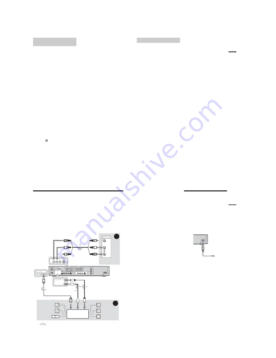
Step 4: Connecting the Audio Cords
Select one of the following patterns
A
or
B
, according to the input jack on your TV monitor, projector,
or AV amplifier (receiver). This will enable you to listen to sound.
A
Connecting to audio L/R input jacks
This connection will use your TV’s or stereo amplifier’s (receiver’s) two speakers for sound. You can
enjoy the following surround effects (page 64).
• TV: Dynamic, Wide, Night
• Stereo amplifier (receiver): Standard, Night
B
Connecting to a digital audio input jack
If your AV amplifier (receiver) has a Dolby
*1
Digital, DTS
*2
, or MPEG audio decoder and a digital input
jack, use this connection. You can enjoy Dolby Digital (5.1ch), DTS (5.1ch), and MPEG audio (5.1ch)
surround effects.
* The yellow plug is used for video signals (page 16).
AERIAL
~
AC IN
IN
OUT
COMPONENT
VIDEO OUT
PB/
CB
Y
PR/
CR
LINE
2
OUT
LINE
4
IN
LINE 1 - TV
VIDEO
-AUDIO
S VIDEO
R
L
VIDEO
-AUDIO
S VIDEO
R
L
DIGITAL
OUT
HDMI OUT
COAXIAL
OPTICAL
PCM/DTS/MPEG/DOLBY DIGITAL
LINE 3
VIDEO
AUDIO
INPUT
L
R
LINE
2
OUT
VIDEO
-AUDIO
S VIDEO
R
L
B
A
DIGITAL
OUT
COAXIAL
OPTICAL
PCM/DTS/MPEG/DOLBY DIGITAL
HDMI OUT
AV amplifier (receiver)
with a decoder
(red)
TV, projector, or AV
amplifier (receiver)
Audio/video cord
(supplied)
: Signal flow
Coaxial digital cord (not supplied)
to DIGITAL OUT (COAXIAL or OPTICAL)
to LINE 2 OUT (R-AUDIO-L)
Optical digital cord
(not supplied)
Rear (L)
DVD recorder
(white)
(yellow)
*
(yellow)
(white)
(red)
[Speakers]
Front (L)
[Speakers]
to coaxial or optical/HDMI digital input
Rear (R)
Front (R)
Subwoofer
or
Centre
HDMI cord
(not supplied)
to HDMI OUT
(RDR-HXD910
only)
21
H
ook
up
s
and
S
e
tti
n
g
s
z
Hint
For correct speaker location, see the operating
instructions supplied with the connected components.
b
Notes
• Do not connect your TV’s audio output jacks to the
LINE IN (R-AUDIO-L) jacks at the same time. This
will cause unwanted noise to come from your TV’s
speakers.
• In the connection
A
, do not connect the LINE IN (R-
AUDIO-L) and LINE 2 OUT (R-AUDIO-L) jacks to
your TV’s audio output jacks at the same time. This
will cause unwanted noise to come from your TV’s
speakers.
• In the connection
B
, after you have completed the
connection, make the appropriate settings under
“Audio Connection” in “Easy Setup” (page 25).
Otherwise, no sound or a loud noise will come from
your speakers.
• With the connection
B
, the surround sound effects of
this recorder cannot be used.
• When you connect the recorder to an AV amplifer
(receiver) using an HDMI cord (RDR-HXD910 only),
you will need to do one of the following:
– Connect the AV amplifier (receiver) to the TV with the
HDMI cord.
– Connect the recorder to the TV with a video cord other
than HDMI cord (component video cord, SVIDEO
cord, or audio/video cord).
*1
Manufactured under license from Dolby Laboratories.
“Dolby,” and the double-D symbol are trademarks of
Dolby Laboratories.
*2
“DTS” and “DTS Digital Out” are trademarks of
Digital Theater Systems, Inc.
Step 5: Connecting the
Mains Lead
Connect the supplied mains lead to the AC IN
terminal of the recorder. Then plug the recorder
and TV mains leads (power cords) into the mains.
After you connect the mains lead,
you must wait
for a short while before operating the
recorder.
You can operate the recorder once the
front panel display lights up and the recorder
enters standby mode.
If you connect additional equipment to this
recorder (page 26), be sure to connect the mains
lead after all connections are complete.
~
AC IN
to mains
to AC IN
1
2
Содержание RDR-GXD310
Страница 6: ...MEMO 6 ...
Страница 36: ...1 30E MEMO ...
Страница 103: ...MEMO 5 10E ...
Страница 109: ...6 6E MEMO ...


