5-7
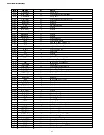
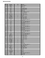
RDR-GX220/GX330
Pin No.
Pin name
I/O
Function
B11
HADRS[27]
O
Output of address 27
B12
HADRS[23]
O
Output of address 23
B13
HADRS[20]
O
Output of address 20
B14
HADRS[16]
O
Output of address 16
B15
HADRS[12]
O
Output of address 12
B16
HADRS[8]
O
Output of address 8
B17
MSBS
—
Fixed at “L”
B18
MSDATA[2]
—
Fixed at “L”
B19
MSCLK
—
Fixed at “L”
B20
SCLK[0]
—
UART(CSIO)/GPIO
B21
TX[1]
—
UART(CSIO)/GPIO
B22
RTS[2]
—
Fixed at “H”
B23
DVSS
Digital GND
B24
PCO
O
Not used
B25
AHVDD
Power supply input (Analog 3.3V)
C1
AT1DATA[5]
—
Input/output of data 5
C2
AT1DATA[10]
—
Input/output of data 10
C3
AT1DATA[13]
—
Input/output of data 13
C4
AT1DATA[15]
—
Input/output of data 11
C5
AT1IORDY
I
Input of i/o ready
C6
AT1ADR[0]
O
Output of devise address 0
C7
AT1CS[0]
O
Output of chip select signal 0
C8
HDACK[0]
—
Output of transfer acknowledge signal/GPIO 0
C9
HCS[0]
O
Output of chip select signal 0
C10
HCS[5]
—
Output of chip select signal/GPIO 5
C11
HADRS[28]
O
Output of address 28
C12
HADRS[24]
O
Output of address 24
C13
HADRS[19]
O
Output of address 19
C14
HADRS[15]
O
Output of address 15
C15
HADRS[11]
O
Output of address 11
C16
HADRS[6]
O
Output of address 6
C17
MSDATA[1]
—
Fixed at “L”
C18
CTS[3]
—
Not used
C19
SCLK[1]
—
UART(CSIO)/GPIO
C20
CTS[0]
—
UART(CSIO)/GPIO
C21
RTS[3]
—
Fixed at “H”
C22
RX[2]
—
UART(CSIO)/GPIO
C23
AHVSS
Digital GND
C24
RX[1]
—
UART(CSIO)/GPIO
C25
HDATA[15]
—
Input/output of data 15
D1
AT1DATA[6]
—
Input/output of data 6
D2
AT1DATA[9]
—
Input/output of data 9
D3
AT1DATA[2]
—
Input/output of data 2
D4
AT1DATA[0]
—
Input/output of data 0
D5
AT1DIOR
O
Output of I/O read signal
D6
AT1ADR[1]
O
Output of devise address 1
D7
AT1CS[1]
O
Output of chip select signal 1
D8
HDREQ[1]
—
Not used
D9
HWS[1]
O
Fixed at “H”
D10
HCS[3]
—
Fixed at “H”
D11
HADRS[29]
O
Output of address 29
D12
HADRS[25]
O
Output of address 25
D13
HADRS[18]
O
Output of address 18
D14
HADRS[14]
O
Output of address 14


