2-28
PFM-42B2/42B2E
1.
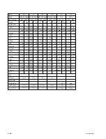
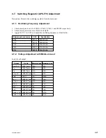
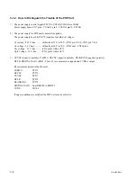
Apply AC 100 VAC-240 VAC to CN61 of switching regulator
Applied voltage
Output voltage location
ADJ
Specification
2.
_
St-by 5 V (CN9002
1
-
2
)
RV203
5.05
±
0.05 V
3.
3.3 V between PFC go
PFC (C112)
RV301
385
±
2 V
(CN7 pin-
!/
and GND)
4.
3.3 V between 26 V ON
26 V output voltage
RV201
26
±
0.1 V
(CN9003 pin-
8
and GND)
(CN9003 pin-
1
and GND)
5.
3.3 V between Vcego
Vcc (5 V) output voltage
RV270
5.18
±
0.02 V
(CN7 pin-
8
and GND)
(CN23 pin-
3
and GND)
6.
3.3 V between Vcego
A13.5 V output voltage
RV202
13.8
±
0.02 V
(CN7 pin-
8
and GND)
(CN9001 pin-
7
and GND)
7.
1.00 V between Vrs
Vs output voltage
RV802
Fully counterclockwise
(CN7 pin-
!]
and GND)
(CN23 pin-
8
and GND)
RV801
79.6
±
0.05 V
and 3.3 V between Vsago
RV802
80
±
0.1 V
(CN7 pin-
6
and GND)
Va output voltage
RV803
Fully counterclockwise
(CN23 pin-
1
and GND)
RV860
48.0
±
0.05 V
RV803
50
±
0.1 V
8.
Set the Va load to 1.0 A.
Iak (CN7
!;
-GND)
RV861
0.60
±
0.01 V
9.
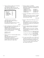
Change the Vrs and Vra in the range of .05 V to 2.0 V and check to see that the Vs and Va output
voltage remain in the variable range.
If not, repeat the adjustment from step 7.
Vs and Va output voltage variable range
Vrs, Vra
Vs (V)
Va (V)
0.5 V
75
±
1.9 %
40
±
3.0 %
1.0 V
80
±
1.9 %
50
±
3.0 %
2.0 V
90
±
1.9 %
70
±
3.0 %
APS-179 board
CN9004
RV270
1
1
1
1
1
1
1
1
1
1
1
1
1
1
RV202 PH107
RV102
RV150
Q504
C112
Q113
Q302
B side mount
C122
CN9001
CN9002
CN9003
CN23
CN6
CN7
RV203
RV201
PH101
PH111
RV101
Q108
Q704
RV950
Q504
PH902
RV901
RV861
RV860
RV801
RV803
RV802
CN61
A SIDE
Содержание PFM-42B2
Страница 8: ......
Страница 22: ......
Страница 58: ...4 4 PFM 42B2 42B2E SLR 325VCT31 CATHODE ANODE UDZS TE17 5 6B UZD TE 17 7 5B CATHODE ANODE Diode ...
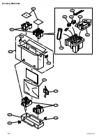
Страница 64: ...5 6 PFM 42B2 42B2E Packing Materials 207 206 202 201 202 212 214 204 203 204 205 208 213 209 211 210 215 ...
Страница 102: ......
Страница 136: ......
Страница 138: ...Sony Corporation B P Company 9 870 315 01 English 02GS16 1 Printed in Japan 2002 7 ...


