2-11
PFM-42B2/42B2E
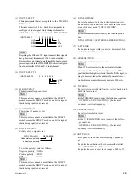
Wide
(Sharp)
Narrow
(Soft)
Frequency
bandwidth
0 1 2 3 4 5 6 7 8 9 10 11
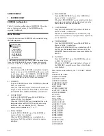
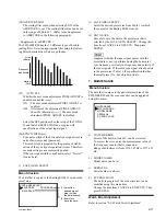
(24)APERTURE LOW
The scaling filter value when selecting LOW of the
APERTURE, is set. The scaling filter value can be set
in the range of 000 to 011. (Refer to the Supplement
to APERTURE in the following paragraph.)
< Supplement to APERTURE >
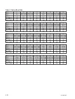
The PFM-42B2/B2E has the 12 different types of built-in
scaling filter. Select an appropriate filter using the follow-
ing filter characteristics chart as a guideline.
(25)
AUTO PLL
Whether the user menu adjustment PIXEL ADJUST is
enabled or disabled, is set.
ON : The user menu adjustment PIXEL ADJUST is
enabled.
OFF : All items of the adjustment PIXEL ADJUST
show the indication [
___
]. The user menu
adjustment PIXEL ADJUST is disabled.
Select the OFF position when the setup of the TOTAL
H and that of RESOLUTION do not agree with
specifications of the actual input signal.
(26)SYNC WIDTH (
µ
s)
Sync pulse width of the horizontal sync signal is set in
units of microseconds [
µ
seconds].
This menu item is prepared for the purpose of stabili-
zation of the sync signal separation circuit. Therefore,
accurate setting is not necessarily needed.
If the sync signal width is not known, select “Not set”
(source data).
c)
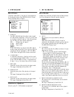
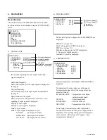
SAVE AREA SELECT
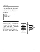
Menu Structure
The data that is copied in the Editing RAM, is saved in the
preset area.
SAVE AREA SELECT
SAVE AREA
DATA SAVE
: PROGRAM1
(1) Select the
desired preset
area to which
the data is saved.
(2) Execute to
save the data.
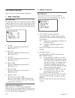
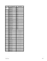
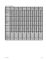
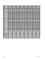
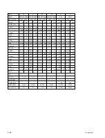
(1) SAVE AREA SELECT
Select the desired preset area from Table 1 to which
the content of the Editing RAM is saved.
(2) DATA SAVE
Execute to save the data to the preset area that is
selected by the SAVE AREA SELECT. Change the
item from CANCEL to EXECUTE. Then press
ENTER.
n
Judgment whether the input signal agrees with the
preset data or not, is performed using the horizontal
sync frequency, vertical sync frequency and polarity of
the sync signals. If the same sync signal already exists
in the preset area (Table 1), the specification that has
the small preset No., has a higher priority.
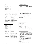
7. MAINTENANCE
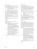
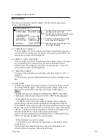
Menu Structure
The data that is unique to the particular machine of the
PFM-42B2/B2E and the scan converter can be upgraded
using this menu.
a)
WATCH ERROR
Errors of the built-in watch IC can be corrected.
To correct the error, enter the measurement value of
the frequency counter that is connected.
Range of adjustment is from 32761.85 Hz to 32774.25
Hz.
b) MODEL NAME
Model name can be set.
c)
SERIAL No.
Serial number can be set.
d) SC PROG LOAD
The built-in program of the scan converter can be
modified using this menu item.
Change the item from CANCEL to EXECUTE. Then
press ENTER.
Watch Error Adjustment
Refer to section “2-6. Watch Error Adjustment”.
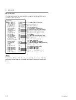
MAINTENANCE
WATCH ERROR
MODEL NAME
SERIAL No.
SC PROG LOAD
Содержание PFM-42B2
Страница 8: ......
Страница 22: ......
Страница 58: ...4 4 PFM 42B2 42B2E SLR 325VCT31 CATHODE ANODE UDZS TE17 5 6B UZD TE 17 7 5B CATHODE ANODE Diode ...
Страница 64: ...5 6 PFM 42B2 42B2E Packing Materials 207 206 202 201 202 212 214 204 203 204 205 208 213 209 211 210 215 ...
Страница 102: ......
Страница 136: ......
Страница 138: ...Sony Corporation B P Company 9 870 315 01 English 02GS16 1 Printed in Japan 2002 7 ...

